
Energy-saving novel ceramic slurry granulation process and equipment for same

A technology of ceramic slurry and ceramic raw materials, which is applied in the direction of liquid separation into beads and granulation, which can solve the problems of easy deformation and cracking of bricks, increase of sintering time, and long molding time, so as to ensure energy recycling, reduce energy consumption, and shape fast effect

Active Publication Date: 2014-02-05
GUANGDONG JUMPER THERMAL TECH
View PDF4 Cites 3 Cited by
  • Summary
  • Abstract
  • Description
  • Claims
  • Application Information

AI Technical Summary

Problems solved by technology

[0003] However, in the above-mentioned existing ceramic slurry granulation process, the high-temperature hot air for evaporating moisture in the ceramic slurry needs to burn fuel to produce, and the temperature of the high-temperature hot air must reach more than 500 degrees before it can be used for dehydration of the ceramic slurry, so it needs to consume a large amount of fuel and energy
Moreover, the ceramic powder particles formed by the above-mentioned existing ceramic slurry granulation process are open and hollow, and contain a large amount of air in the ceramic powder particles. During molding, the press needs to be exhausted many times, and the molding time is long; For large output, it is necessary to increase the number of presses, which invisibly occupies more workshop space; and the structure of the ceramic body formed by opening and hollow ceramic powder particles is loose, and the shrinkage is large during firing, and the brick is easy to deform and crack, which increases the sintering process. time

Method used


Image

  • Energy-saving novel ceramic slurry granulation process and equipment for same

Examples


Embodiment Construction

[0013] In the following, the present invention will be further described in conjunction with the accompanying drawings and specific embodiments, so as to understand more clearly the technical idea claimed in the present invention.

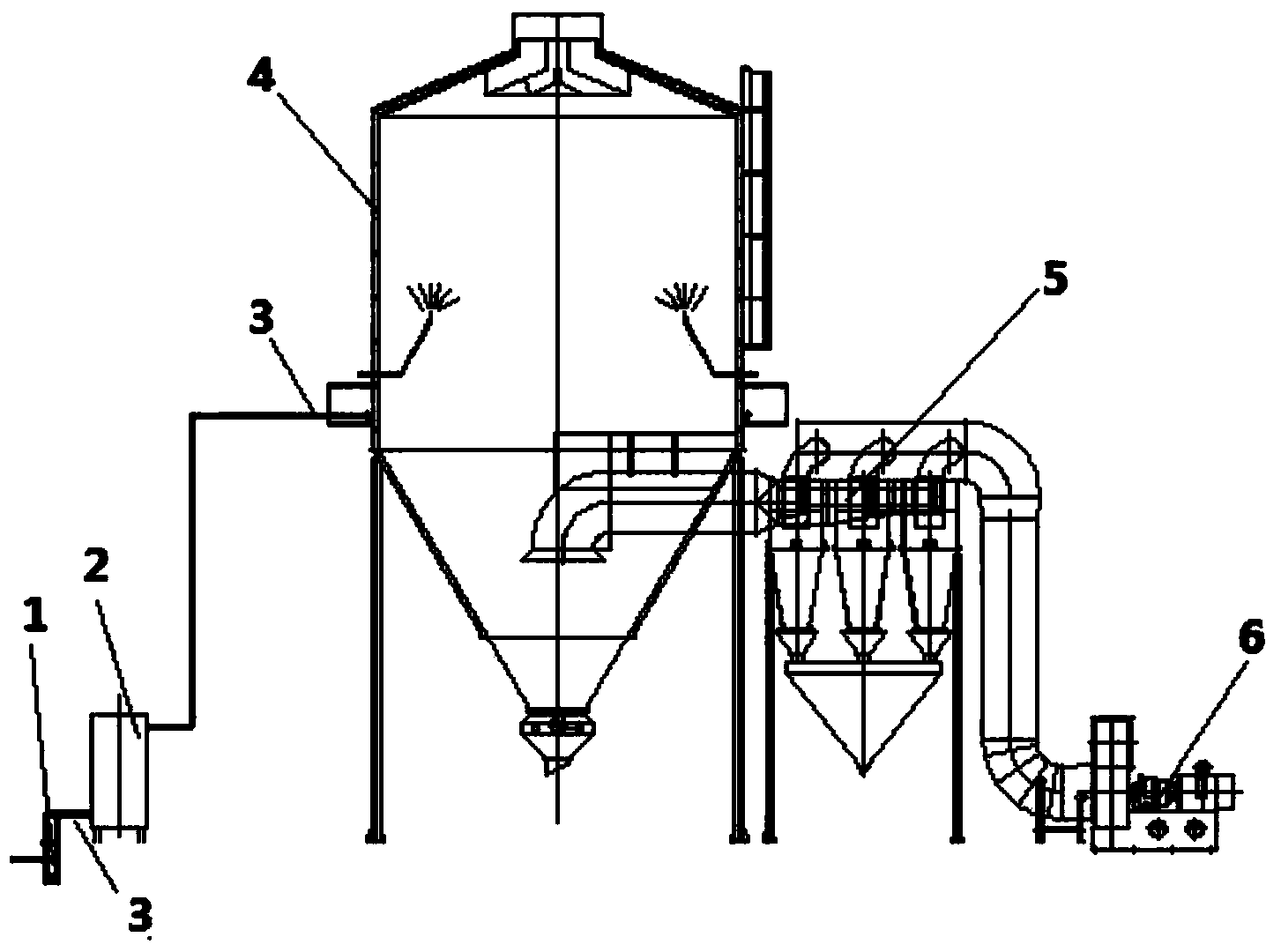
[0014] Such as figure 1 Shown is the equipment used for the energy-saving new ceramic slurry granulation process of the present invention, including a plunger pump 1 for pumping ceramic slurry, a heat exchanger 2 for preheating the ceramic slurry and a spray Tower 4, the plunger pump 1 is connected to the heat exchanger 2 through the slurry pipe 3, and the heat exchanger 2 is also connected to the nozzle of the spray tower 4 through the slurry pipe 3; the other side of the spray tower 4 is also provided with a The cyclone dedusting device 5 for evaporating moisture in the spray tower 4 and discharging the fine dust and tail gas in the spray tower 4 is connected with an induced draft fan 6 .

[0015] The present invention is a novel energy-saving c...


PUM


Abstract

The invention discloses an energy-saving novel ceramic slurry granulation process and equipment for the same. The process specifically comprises the steps of changing ceramic raw materials into ceramic slurry through ball milling, ageing, pumping into a slurry pipe in a high-pressure environment by a plunger pump, preheating to the temperature of 80-500 DEG C, and spraying into a spray tower by a spray nozzle. The equipment comprises the plunger pump, a heat exchanger and the spray tower, wherein the plunger pump is connected with the heat exchanger through the slurry pipe, and the heat exchanger is connected with the spray nozzle of the spray tower through the slurry pipe. According to the process and the equipment, the ceramic slurry is preheated to the temperature of 80-500 DEG C and then is sprayed into the spray tower, the moisture of the ceramic slurry can be evaporated through the heat of the ceramic slurry in a low-pressure environment in the spray tower, and the consumption of a lot of energy sources is reduced, so that the process and the equipment are energy-saving and environmental-friendly; ceramic granules produced by the process disclosed by the invention are solid granules and have the advantages that the fluidity is good, the molding speed is high, the firing cycle is short, a molding blank difficultly deforms and cracks, and the like; the preheating heat of the process can be residual heat generated by a kiln, namely heat contained in exhaust gases of the kiln, and energy sources can be recycled, so that the process is energy-saving.

Description

technical field [0001] The invention belongs to the technical field of ceramic slurry granulation, and in particular relates to a ceramic slurry granulation process and equipment used in the ceramic slurry granulation process. Background technique [0002] The existing ceramic slurry granulation process is: spray the ceramic slurry at room temperature into the spray tower, and conduct heat exchange through the high-temperature hot air coming down from the top of the spray tower, and evaporate the ceramic slurry sprayed into the spray tower The water in the spray tower forms open hollow ceramic powder particles, and the open hollow ceramic powder particles fall into the lower hopper of the spray tower due to their own gravity, and the water vapor, fine dust and other exhaust gases evaporated in the spray tower are sucked away by the fan . [0003] However, in the above-mentioned existing ceramic slurry granulation process, the high-temperature hot air for evaporating moistur...

Claims


Application Information

Patent Timeline
IPC IPC(8): B01J2/02
Inventor 万鹏
Owner GUANGDONG JUMPER THERMAL TECH
Learn More