Dual-channel porous turbulence pressure relief drilling tool for soft coal rock drilling, and construction method of drilling tool

A dual-channel, soft coal-rock technology, applied to drilling equipment and methods, drilling tools, percussion drilling, etc., can solve the problems of easy blockage, damage, and low drilling efficiency of drilling holes, and achieve the effect of heat dissipation

Active Publication Date: 2014-02-05
HENAN POLYTECHNIC UNIV
View PDF6 Cites 30 Cited by
  • Summary
  • Abstract
  • Description
  • Claims
  • Application Information

AI Technical Summary

Problems solved by technology

[0002] At present, underground gas drainage is the main technical means of mine gas control. Underground gas drainage is premised on drilling construction, which mainly includes gas drainage drilling in the coal seam and gas drainage drilling through layers. For geological conditions In complex weak coal and rock mass, during drilling construction, the hole wall shrinks and is severely damaged. In addition, gas-containing coal jet holes occur frequently, and blockages are easily formed in the borehole, resulting in loss of slag discharge space, drill sticking, and drill breakage. Frequent, resulting in shallow drilling depth, low drilling efficiency and frequent accidents in the hole, as a result, the construction progress of gas drainage and the safe production of coal mines are seriously affected, and certain economic losses are brought to the mine.
Currently commonly used drilling tools, the slag discharge channel is the annular space between the borehole wall and the drill pipe. For drilling in weak coal and rock masses with complex geological conditions, the deformation and damage of the hole wall will affect the slag discharge space of the drill hole. Larger, easy to block the borehole, making drilling impossible

Method used


Image

  • Dual-channel porous turbulence pressure relief drilling tool for soft coal rock drilling, and construction method of drilling tool
  • Dual-channel porous turbulence pressure relief drilling tool for soft coal rock drilling, and construction method of drilling tool
  • Dual-channel porous turbulence pressure relief drilling tool for soft coal rock drilling, and construction method of drilling tool

Examples


Embodiment 1

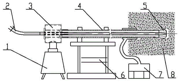
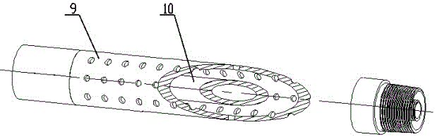
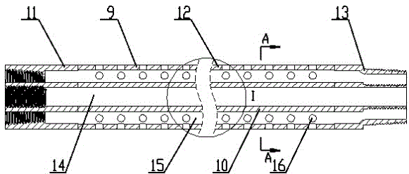
[0031] Embodiment one: if Figure 1 to Figure 9 As shown, the present invention is a dual-channel porous turbulent flow pressure relief drilling tool for soft coal and rock drilling and a construction method thereof, including a dual-channel porous turbulent flow pressure relief drill rod 4, a dual-channel drill bit 5, and a rotary slag discharge at the drill tail. Device 3, the drill tail rotary slagging device 3 is connected to the dual-channel porous turbulent flow pressure relief drill pipe 4 on the drilling rig, and the dual-channel drill bit 5 is installed on the front end of the dual-channel porous turbulent flow pressure relief drill pipe 4 . The double-channel porous turbulent flow pressure relief drill pipe 4 is composed of a porous outer drill pipe body 9 and an inner pipe 10 . The porous outer drill rod body 9 is composed of an internally threaded joint 13, a porous rod body 12 and an externally threaded joint 11. A plurality of small holes 16 are arranged on the r...

Embodiment 2

[0038] Embodiment two: if Figure 10 ~ Figure 13 As shown, the difference from Embodiment 1 is that the outer surface of the outer drill rod body 9 is provided with a helical rib 28, and the helical rib adopts a welding helical blade or a plasma coating process. When the rod rotates, the helical ribs on the surface of the drill pipe form a spiral conveying state, which can realize auxiliary slag discharge, and at the same time, it is beneficial to the surface of the drill pipe to dissipate heat and avoid the high temperature of the drilling tool caused by heat accumulation; on the other hand, the helical ribs on the surface of the drill pipe It can effectively improve the strength of the drill rod body 9 outside the hole, and indirectly prolong the service life of the drill rod. The construction method of embodiment two is the same as embodiment one.

Embodiment 3

[0039] Embodiment three: as Figure 14 ~ Figure 17 As shown, the difference from Embodiment 1 and Embodiment 2 is that the outer surface of the outer drill pipe body 9 is provided with a helical groove 29. The function of the helical groove is similar to that of Example 2, but its auxiliary slagging ability is weak, and its important The function is to exert its heat dissipation function in the stuck drill area, which can effectively prevent drilling gas combustion, drilling CO poisoning and other in-hole accidents formed in the stuck drill area. The construction method of embodiment three is the same as embodiment one and embodiment two.


PUM


Abstract

The invention discloses a dual-channel porous turbulence pressure relief drilling tool for soft coal rock drilling, and a construction method of the drilling tool. The drilling tool comprises a drilling tail rotating slag tapping device, a dual-channel porous turbulence pressure relief drilling rod and a dual-channel drilling bit, wherein the drilling tail rotating slag tapping device is connected with the dual-channel porous turbulence pressure relief drilling rod on a drilling machine, and the dual-channel drilling bit is mounted at the front end of the dual-channel porous turbulence pressure relief drilling rod. The drilling tool is mainly used for easy-to-shrink and broken soft coal rock drilling. The construction method of the drilling tool comprises the steps that the drilling machine and an air supply system are started; an air flow enters an inner channel of the dual-channel porous turbulence pressure relief drilling rod and reaches the bottom of a drilling hole; and the air flow carries drilling cuttings to reverse out along an outer channel of the dual-channel porous turbulence pressure relief drilling rod to enter a dust collector connected with the drilling tail rotating slag tapping device. The drilling tool is novel in design; deslagging is accomplished in an annular space in the drilling rod, so that influences of drilling hole shrinkage and drilling hole damage on a drilling hole deslagging space can be avoided effectively; and due to the porous characteristic of the surface of the drilling rod, stress between a rod body in a drilling hole blocking area and coal slag can be released effectively, the stacked drilling cuttings can be evacuated, and heat gathering on the surface of the drilling rod can be prevented.

Description

technical field [0001] The invention belongs to the technical fields of gas drainage drilling construction in outburst coal seams of coal mines and soft rock drilling construction, and in particular relates to a dual-channel porous turbulent flow pressure relief drilling tool for drilling soft coal rocks and a construction method thereof. Background technique [0002] At present, underground gas drainage is the main technical means of mine gas control. Underground gas drainage is premised on drilling construction, which mainly includes gas drainage drilling in the coal seam and gas drainage drilling through layers. For geological conditions In complex weak coal and rock mass, during drilling construction, the hole wall shrinks and is severely damaged. In addition, gas-containing coal jet holes occur frequently, and blockages are easily formed in the borehole, resulting in loss of slag discharge space, drill sticking, and drill breakage. Frequent, resulting in shallow drillin...

Claims


Application Information

Patent Timeline
Patent Type & Authority Applications(China)
IPC IPC(8): E21B3/00E21B17/00E21B11/00E21B21/06
Inventor 王永龙孙玉宁宋维宾
Owner HENAN POLYTECHNIC UNIV
Why Eureka
Try Eureka