Environment-friendly tandem type drying and calcining kiln

A calcining kiln and tandem technology, which is applied in the improvement field of industrial lifting plate drying and calcining equipment, can solve the problems of dust pollution, leakage of the tandem drying and calcining kiln system, etc., so as to avoid leakage, improve environmental pollution problems and structure. simple effect

Active Publication Date: 2014-02-05
HUBEI JINLU ENERGY SAVING LTD CO
View PDF4 Cites 3 Cited by
  • Summary
  • Abstract
  • Description
  • Claims
  • Application Information

AI Technical Summary

Problems solved by technology

[0003] The purpose of the present invention is to solve the problem that the series-connected drying and calcining kiln system is prone to leakage and dust pollution, and to provide an environment-friendly serial drying and calcining kiln

Method used


Image

  • Environment-friendly tandem type drying and calcining kiln
  • Environment-friendly tandem type drying and calcining kiln
  • Environment-friendly tandem type drying and calcining kiln

Examples


example 1

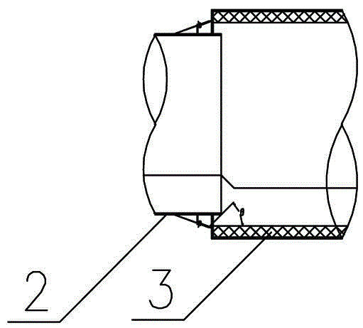
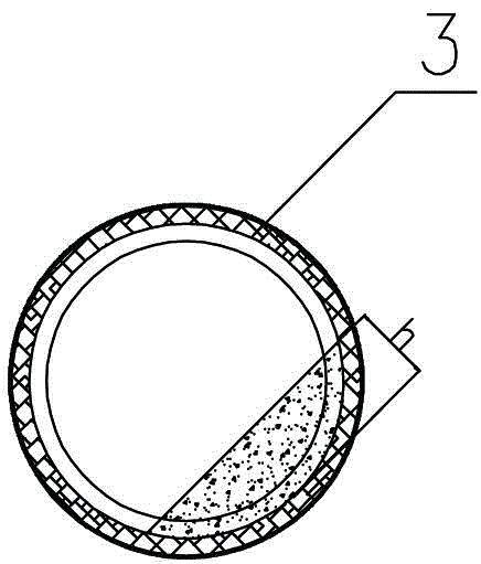
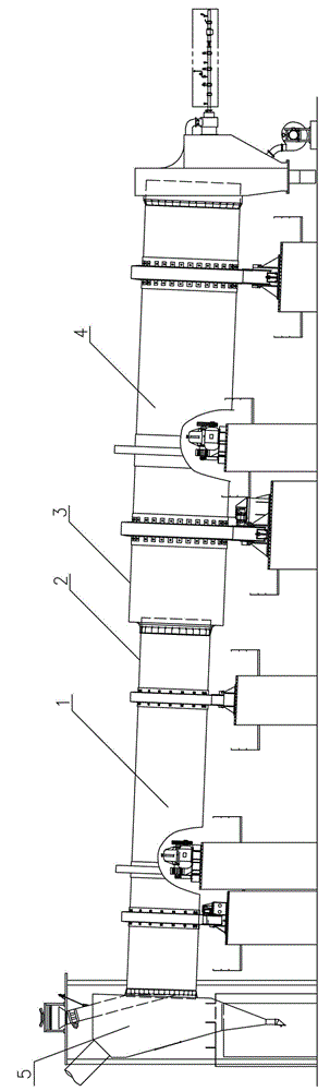
[0027] Example 1: see image 3 —5. The present invention includes a rotary dryer 1 and a rotary calciner 3, both of which are provided with a cylinder, wherein the diameter of the dryer cylinder 2 is relatively small, and its butt joint is placed in the calciner cylinder 3, especially Yes: 21 pusher plates 5 are inserted into the ring on the butt end face of the dryer barrel 2, and the pusher plates 5 are arranged to push forward along the axial direction.

[0028] In this embodiment, the pusher plate 5 is arranged at an angle of 21° (adjustable in the range of 18-26°) to the end surface of the dryer barrel 2, that is, t=the pitch of the pusher plate is 4m.

[0029] In this embodiment, the pushing plate 3 is provided with a card slot, and the card slot is installed on the end face ring of the dryer barrel 1 and welded as a whole.

[0030] The length L=kh / tgθ of the pushing plate 3 described in this embodiment, the height H=kQ×tgθ×(36.896n×t×a×p×n×N) -1 . In the above formul...

example 2

[0045] Example 2: see image 3 —5. The present invention includes a rotary dryer 1 and a rotary calciner 3, both of which are provided with a cylinder, wherein the diameter of the dryer cylinder 2 is relatively small, and its butt joint is placed in the calciner cylinder 3, especially Yes: 18 pusher plates 5 are inserted into the ring on the butt end face of the dryer barrel 2, and the pusher plates 5 are arranged to push forward along the axial direction.

[0046] In this embodiment, the pusher plate 5 is arranged at an angle of 26° to the end surface of the dryer barrel 2, that is, t=the pitch of the pusher plate is 3m.

[0047] In this embodiment, 18 slots are uniformly distributed on the end face ring of the dryer barrel 2, and the pushing plate 5 is inserted into the slots and fixed by welding.

[0048] The length L=kh / tgθ of the pushing plate 3 described in this embodiment, the height H=kQ×tgθ×(36.896n×t×a×p×n×N) -1 . In the above formula:

[0049] k-safety factor, g...


PUM


Abstract

The invention relates to an improved technology of industrial raising plate drying and calcining equipment, and provides an environment-friendly tandem type drying and calcining kiln. The environment-friendly tandem type drying and claiming kiln comprises a rotary dryer and a rotary calcining kiln, wherein both of the rotary dryer and the rotary calcining kiln are provided with cylinder bodies; the cylinder bodies are butted with each other; the diameter of the cylinder body of the dryer is relatively small; the abutting section of the cylinder body of the dryer is arranged in the cylinder body of the calcining kiln. The environment-friendly tandem type drying and calcining kiln is characterized in that a plurality of material pushing plates are inserted in a circular ring on the abutting end surface of the cylinder body of the dryer, are arranged in a forward material pushing manner in the axial direction, and are tilted to the end surface of the cylinder body of the dryer. The environment-friendly tandem type drying and calcining kiln solves the problem that a material leaks easily from the joint of the dryer and the calcining kiln of the conventional tandem type drying and calcining kiln, so as to avoid dust pollution, and be widely applied to building materials, chemical engineering and the metallurgical industry.

Description

technical field [0001] The invention relates to the improvement technology of industrial lifting plate drying and calcining equipment, in particular to an environment-friendly serial drying and calcining kiln. Background technique [0002] The calcination of high-humidity materials, such as calcination of calcium carbide slag with 55% water content into CaO; the non-toxic calcination of calcium arsenate slag with 75% water content produced by copper smelting flue gas acid production, etc., must be dried and dehydrated before entering the calcination process. However, the slow rotating calcination process in a single kiln restricts the drying efficiency. Therefore, an ultra-long kiln body must be used to solve the drying requirements with most of the length. The speed of the machine is 10-20 times that of the kiln body, and the drying efficiency is more than 10 times that of the kiln. If the dryer and the kiln are connected in series, and each has its own advantages, the kil...

Claims


Application Information

Patent Timeline
Patent Type & Authority Applications(China)
IPC IPC(8): F27B7/06F27B7/16F26B11/04
Inventor 熊承庆黄萌李晶
Owner HUBEI JINLU ENERGY SAVING LTD CO
Why Eureka
Try Eureka