Eureka AIR delivers breakthrough ideas for toughest innovation challenges, trusted by R&D personnel around the world.

0.5THz corrugated horn antenna and preparation method using MEMS technology

A technology of corrugated horns and antennas, applied in waveguide horns, optical waveguide coupling, TV system components, etc., can solve the problems of difficult frequency coverage and high cost, and achieve the effect of easy array formation, low cost, and reduced impact

Inactive Publication Date: 2014-02-05
BEIJING INSTITUTE OF TECHNOLOGYGY
View PDF4 Cites 6 Cited by
  • Summary
  • Abstract
  • Description
  • Claims
  • Application Information

AI Technical Summary

Problems solved by technology

At present, domestic machined horn antennas are difficult to cover the frequency band of 0.5THz due to the limitation of processing technology.
Although foreign countries can prepare 0.5THz horn antennas through precise machining processes, the cost is very high

Method used


Image

  • 0.5THz corrugated horn antenna and preparation method using MEMS technology
  • 0.5THz corrugated horn antenna and preparation method using MEMS technology
  • 0.5THz corrugated horn antenna and preparation method using MEMS technology

Examples


Embodiment

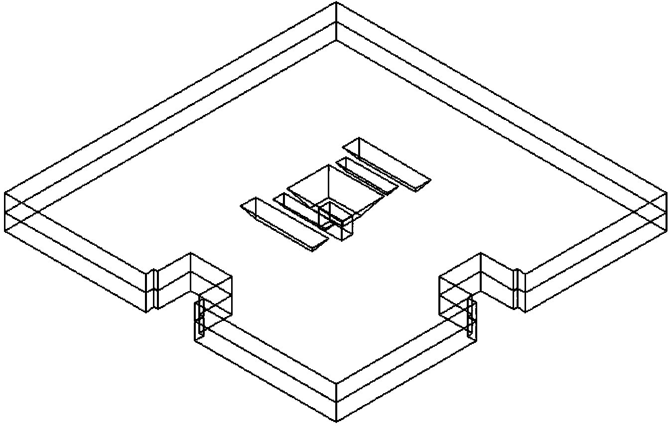
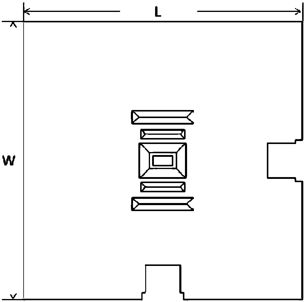
[0031] like figure 1 , figure 2 , image 3 As shown, a 0.5THz corrugated horn antenna, the antenna is a cuboid (8mm×8mm×0.8mm), and there is a positioning groove on the two adjacent sides of the cuboid, which is mainly used for pre-processing under the integrated process. There is a fixed card slot for the antenna fixture; there is a horn structure at the center of the upper surface of the cuboid. The size of the horn mouth is 1.34mm×1.02mm, shrinking at an angle of 54.7° with the silicon wafer plane, and the length of the horn is 0.4 mm; below the horn structure is a waveguide, the waveguide model WR2.2, the cross-sectional size is 0.56mm×0.28mm), and the length is 0.4mm; the horn structure and the waveguide are connected by steps, and there are two on both sides of the horn structure. A V-shaped corrugated groove, the notch dimensions are 1.25mm×0.25mm and 1.75mm×0.375mm respectively, shrinking at an angle of 54.7° with the silicon wafer plane.

[0032] A method for prep...


PUM

PropertyMeasurementUnit
Thicknessaaaaaaaaaa

Abstract

The invention relates to a 0.5THz corrugated horn antenna and a preparation method using an MEMS technology. The 0.5THz corrugated horn antenna and the preparation method using the MEMS technology are applicable to a terahertz-band imaging system or a short-distance terahertz communication system. The 0.5THz corrugated horn antenna comprises an expanded horn, V-shaped corrugated grooves, locating grooves and a step on the throat portion of the horn, wherein compared with a waveguide, the horn can improve radiation efficiency and rotation symmetry of a directional diagram; the V-shaped corrugated grooves are used for cutting off a surface current, the gain is effectively increased, and influence of metal structures around the 0.5THz corrugated horn antenna on the performance of the 0.5THz corrugated horn antenna can be reduced; the locating grooves can ensure accurate alignment when installation butt joint of the 0.5THz corrugated horn antenna is carried out; due to the step on the throat portion of the horn, the design freedom of the structure of the horn can be remarkably improved, influence of the alignment error between an upper layer silicon chip and a lower layer silicon chip on the performance of the 0.5THz corrugated horn antenna can be reduced, and the processing yield is improved. According to the thinking design, the 0.5THz corrugated horn terahertz antenna designed and obtained through the thinking is good in applicability, an array can be easily formed, and fixation and testing can be easily carried out. The 0.5THz corrugated horn antenna works within the 450GHz-530GHz frequency band, a standing wave of the 0.5THz corrugated horn antenna is lower than 1.6, the in-band gain is larger than 15dB, and the maximum gain can reach 16.6dB.

Description

technical field [0001] The invention relates to a 0.5THz corrugated horn antenna and a preparation method using MEMS technology, which is suitable for a terahertz band imaging system or a short-distance terahertz communication system. Background technique [0002] Terahertz imaging technology is an important field of terahertz technology application, which can be applied to airport security inspection, product non-destructive testing, etc. At present, terahertz focal plane imaging technology is one of the hotspots in the research of terahertz imaging in the world. Antennas generally used in terahertz focal plane imaging systems include planar helical antennas, horn antennas, monopole or dipole antennas. In the terahertz band, the wavelength of electromagnetic waves is very small, and the absolute size of antennas and passive components is small. Limited by material properties and manufacturing processes, conventional processing techniques cannot fully meet the design of com...

Claims


Application Information

Patent Timeline
IPC IPC(8): H01Q13/02B81B7/02
Inventor 刘埇卢宏达高子健赵鹏飞李庆吕昕
Owner BEIJING INSTITUTE OF TECHNOLOGYGY
Why Eureka
Eureka Blog
Learn More