Self-triggering voltage setting method of spark gap of 500kV series compensation system

A spark gap and self-triggering technology, applied in spark gap adjustment and other directions, can solve the problems of large dispersion of self-triggering voltage, self-triggering of main gap, bypass of series compensation, etc., and achieve the effect of reducing false self-triggering of spark gap.

Active Publication Date: 2014-02-12
ELECTRIC POWER RESEARCH INSTITUTE, CHINA SOUTHERN POWER GRID CO LTD
View PDF5 Cites 8 Cited by
  • Summary
  • Abstract
  • Description
  • Claims
  • Application Information

AI Technical Summary

Problems solved by technology

[0017] Since the 500kV series compensation system was put into operation, whether it is the series compensation gap of GE company or the series compensation gap of SIEMENS company, the problem of series compensation bypass caused by the self-triggering of the main gap has occurred many times
[0019] Through experimental research, it is found that the self-triggering voltage of the flashover gap is highly dispersed under polluted conditions, which is the root cause of the self-triggering of the spark gap in the 500kV series compensation system

Method used


Image

  • Self-triggering voltage setting method of spark gap of 500kV series compensation system
  • Self-triggering voltage setting method of spark gap of 500kV series compensation system
  • Self-triggering voltage setting method of spark gap of 500kV series compensation system

Examples


Embodiment 1

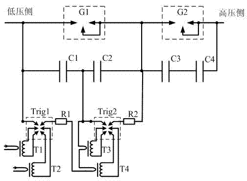
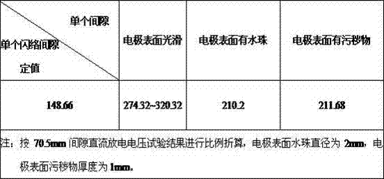
[0037] Balance I circuit and II circuit series compensation are located in Pingguo series compensation station, the series compensation protection level is 190kVp (2.3p.u.), and the self-trigger voltage setting value is 209kVp. The spark gap model is XLSK-30PL, which is composed of two spark gap chambers. The flashover gap self-triggering voltage of each gap chamber is 104.5kVp. Each gap chamber has two trigger gaps, and each trigger gap has a self-triggering voltage setting value It is 52.3kVp. According to the experimental research results, when the electrode surface is smooth and clean, the self-triggering voltage range of the flashover gap is 93~116kVp; ~74.4kVp, that is to say, the normal range of the self-triggering voltage of the entire flashover gap is 186~232kVp. Under abnormal conditions, the self-triggering voltage is 136~148.8kVp; in extreme cases, the self-triggering voltage is 99kVp. Because of this, when the second line of the sky fails, the series compensation...

Embodiment 2

[0048] According to the adjustment strategy proposed by the present invention, the self-triggering value of each flashover gap of the PCS-GAP-160 spark gap produced by Nanjing Nanrui Jibao Electric Co., Ltd. was adjusted to 1.8p.u., and its working reliability was tested.


PUM


Abstract

The invention relates to a self-triggering voltage setting method of a spark gap of a 500kV series compensation system. The spark gap of the series compensation system structurally comprises a self-triggering main gap device G1, a self-triggering main gap device G2, a sealing gap device TRIG1, a sealing gap device TRIG2, a current limiting resistor R1, a current limiting resistor R2, a pulse transformer T1, a pulse transformer T3, a high-insulation pulse transformer T2, a high-insulation pulse transformer T4, a voltage-sharing capacitor C1, a voltage-sharing capacitor C2, a voltage-sharing capacitor C3 and a voltage-sharing capacitor C4. The self-triggering voltage setting method of the spark gap of the series compensation system includes the steps that the single flashover gap distance of the main gap device G1 and the single flashover gap distance of the main gap device G2 are adjusted according to 1.8p.u. series compensation rated voltages, and the flashover gap self-triggering voltages are made to be higher than the sum of the self-triggering voltages of two triggering gaps on a parallel branch. By means of the self-triggering voltage setting method of the spark gap of the 500kV series compensation system, self-triggering of the spark gap in the operating process of the series compensation system can be effectively reduced, the problem of self-triggering voltage reduction caused by dirt accumulation on the surface of a hemispherical flashover gap graphite electrode is solved, and thus the self-protection function of the self-triggering voltages of the series connection spark gap can be achieved.

Description

technical field [0001] The invention is a self-triggering voltage setting method for the spark gap of a 500kV series compensation system, and is a good measure for reducing false self-triggering of the spark gap during the operation of the series compensation system. Applying this method can effectively solve the problem of self-triggering voltage drop caused by dirt, water droplets, burrs, etc. on the graphite electrode in the flashover gap. It is an innovative technology that belongs to the protection strategy of 500kV series compensation system. Background technique [0002] The series compensation capacitor equipment is installed on the ultra-high voltage transmission line. The series capacitor compensates the line reactance, shortens the line electrical distance, improves the transient stability of the transmission system, and increases the transmission capacity. For the China Southern Power Grid, in order to improve the capacity of west-to-east power transmission and ...

Claims


Application Information

Patent Timeline
Patent Type & Authority Applications(China)
IPC IPC(8): H01T21/06
Inventor 蔡汉生刘刚贾磊陈喜鹏胡上茂
Owner ELECTRIC POWER RESEARCH INSTITUTE, CHINA SOUTHERN POWER GRID CO LTD
Why Eureka
Try Eureka