
Time flight imaging spectrum system and method based on compressed sensing and coding transformation

A technology of imaging spectroscopy and compressed sensing, applied in the field of time-of-flight imaging spectroscopy

Active Publication Date: 2014-02-19
NAT SPACE SCI CENT CAS
View PDF3 Cites 36 Cited by
  • Summary
  • Abstract
  • Description
  • Claims
  • Application Information

AI Technical Summary

Problems solved by technology

[0006] The purpose of the present invention is to overcome the defect in the prior art that it is difficult to use point detectors instead of area array detectors to realize time-of-flight four-dimensional spectral imaging, thereby improving a time-of-flight imaging spectral system and method based on compressed sensing and coding transformation

Method used


Image

  • Time flight imaging spectrum system and method based on compressed sensing and coding transformation
  • Time flight imaging spectrum system and method based on compressed sensing and coding transformation
  • Time flight imaging spectrum system and method based on compressed sensing and coding transformation

Examples


Embodiment Construction

[0044] The present invention will be further described now in conjunction with accompanying drawing.

[0045] Before describing the present invention in detail, the related concepts involved in the present invention will be described first.

[0046] Compressed Sensing (CS for short): Compressed sensing can perfectly restore the original signal in a random sampling manner with fewer data samples (far below the limit of the Nyquist / Shannon sampling theorem). The basic steps of compressed sensing include: firstly, using prior knowledge, select a suitable sparse basis Ψ, so that the point spread function x is transformed by Ψ to get x' is the most sparse; when the measured value vector y, measurement matrix A and sparse Under the condition of Ψ, the mathematical model y=AΨx′+e is established, and the convex optimization is carried out through the compressed sensing algorithm. After obtaining x’, the Inverts to x.

[0047]Hadamard transformation: The theoretical model of Hadamar...


PUM


Abstract

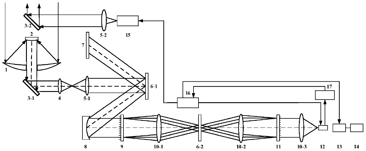
The invention relates to a time flight imaging spectrum system based on compressed sensing and coding transformation. The time flight imaging spectrum system comprises a pulse laser unit, a telescope unit, an imaging lens, a first beam expanding collimating lens, a first digital micro-mirror, a camera, a concave surface collimating mirror, a spectro-grating, a first convergent lens, a second digital micro-mirror, a second convergent lens, a light combining grating, a third convergent lens, a point detector, a Hadamard inverse transformation module, a compression calculation relevance module and a flight time relevance module. The pulse laser unit comprises an active pulse light source, a second beam expanding collimating lens and a second mirror. The telescope unit comprises a concave surface mirror, a convex surface mirror and a first mirror. The flight time relevance module comprises a synchronous control unit and a timescale converter.

Description

technical field [0001] The invention relates to the field of time-of-flight imaging spectroscopy, in particular to a time-of-flight imaging spectroscopy system and method based on compressed sensing and coding transformation. Background technique [0002] Imaging spectroscopy technology combines imaging technology and spectroscopy technology to form a spectral bandwidth detection covering the range from ultraviolet to far infrared. It is mainly used to obtain spatial two-dimensional information and spectral information of the measured target. It is a new type of multi-dimensional information acquisition technology. . The combination of spectral imaging technology and real-time processing technology can quickly provide the ground with the spatial and spectral information of the detection target, improve the response speed, and accurately realize the qualitative research of the target. The rapid development of applications in fields such as crop pest and disease monitoring, w...

Claims


Application Information

Patent Timeline
IPC IPC(8): G01J3/28
Inventor 孙志斌俞文凯代斌姚旭日翟光杰蒋远大杨震孟新
Owner NAT SPACE SCI CENT CAS
Learn More