IGBT driving circuit of converter for electric locomotive

A technology for electric locomotives and driving circuits, applied in electrical components, output power conversion devices, etc., can solve problems such as the inability of IGBT converters to operate safely and reliably, the limited driving capability of integrated drive chips, and the inability to meet flexible adjustment of line protection capabilities.

Active Publication Date: 2014-02-19
BEIJING CED RAILWAY ELECTRIC TECH
View PDF4 Cites 14 Cited by
  • Summary
  • Abstract
  • Description
  • Claims
  • Application Information

AI Technical Summary

Problems solved by technology

[0004] In the prior art, the widely used IGBT drive circuit is an independent integrated drive chip that can be obtained through commercial means; this integrated drive chip not only has limited drive capability, but also is difficult to flexibly adjust the parameters in the line, so this kind of Independently integrated drive chips cannot meet the needs of electric locomotives for flexible adjustment of the driving capability and line protection capabilities of IGBT drive circuits in different application scenarios; on the other hand, due to the harsh electromagnetic environment on electric locomotives, independent integrated drive chips are very It is prone to failure due to electromagnetic interference, so the independent integrated drive chip in the prior art cannot guarantee the safe and reliable operation of the IGBT converter in the complex environment of the electric locomotive

Method used


Image

  • IGBT driving circuit of converter for electric locomotive
  • IGBT driving circuit of converter for electric locomotive
  • IGBT driving circuit of converter for electric locomotive

Examples


Embodiment 1

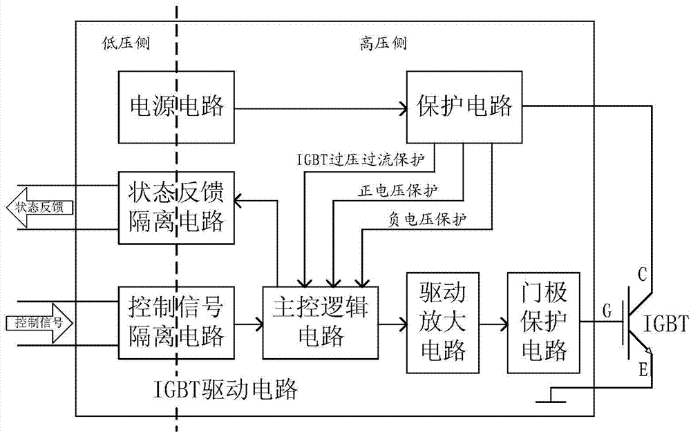
[0101] Such as Figure 1 to Figure 8 As shown, an IGBT driving circuit of a converter for an electric locomotive is connected between the main control unit of the electric locomotive and the IGBT of the converter, and its specific structure can adopt the above-mentioned technical scheme.

Embodiment approach

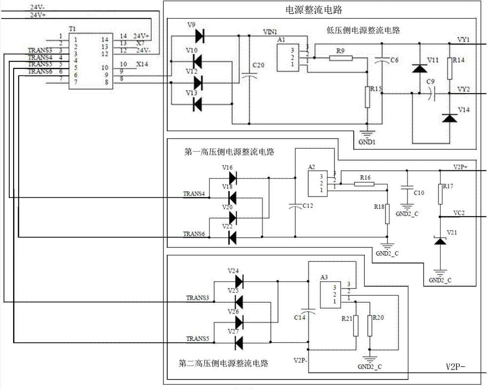
[0103] (1) in figure 2 In the circuit shown, the first pulse transformer T1 can use three 1:1 winding transformers, the isolation voltage is AC1000V, the inductance value is about 300uH at 10kHZ, the resistance value of each winding is less than 100m ohms, and the working frequency is 35kHz.

[0104] (2) in figure 2 In the circuit shown, the first regulated power supply A1, the second regulated power supply A2 and the third regulated power supply A3 can use ST’s LD1086V, and the required + 15V and -15V voltage. The first four diodes V14 and the second one Zener diode V21 can use Fairchild's IN4733, and the required 5V voltage can be obtained by building peripheral circuits.

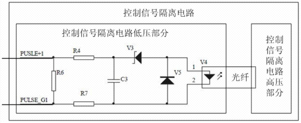
[0105] (3) at image 3 , Figure 4 and Figure 5 In the circuit shown, the first fiber optic transmitter V4 and the second fiber optic transmitter V15 can use AVAGO SFH756V, the first fiber optic receiver V6 and the second fiber optic receiver V2 can use Avago (AVAGO) ) SFH551 / 1-1V, the optical fi...


PUM


Abstract

The invention discloses an IGBT driving circuit of a converter for an electric locomotive. The IGBT driving circuit is characterized in that complete isolation of the high-voltage side and the low-voltage side can be achieved through power voltage isolation, control signal isolation and state feedback signal isolation, an IGBT overvoltage-overcurrent protection circuit, a positive voltage protection circuit, a negative voltage protection circuit and a gate pole protection circuit are adopted to implement further circuit protection, and therefore the IGBT converter can safely and reliably run and can well adapt to the complex environment in the electric locomotive. Meanwhile, the IGBT driving circuit is further characterized in that flexible model selection can be carried out on a voltage-stabilizing diode, a bidirectional transient voltage suppression diode and four avalanche diodes, and therefore the requirements of different application scenarios of the electric locomotive for the circuit protection capacity are flexibly met; in addition, flexible model selection can be further carried out on a second adaptation board resistor RA2, a fourth adaptation board resistor RA4 and a first adaptation board capacitor CA1, and therefore the requirements of the different application scenarios of the electric locomotive for the IGBT driving capacity are flexibly met.

Description

technical field [0001] The invention relates to the field of electric locomotives, in particular to an IGBT driving circuit of a converter for electric locomotives. Background technique [0002] At present, the HXD1, HXD2, HXD1B, HXD2B and other models of heavy-duty AC drive electric locomotives produced in China all use converters based on IGBT (Insulated Gate Bipolar Transistor, insulated gate bipolar transistor) (referred to in this application document as for IGBT converters). The IGBT drive circuit is the key technology for IGBT applications. Its performance directly determines the overall performance of the IGBT converter. Therefore, on the electric locomotive using the IGBT converter, the performance of the IGBT drive circuit is directly related to the safety of the entire electric locomotive. sex and reliability. [0003] On electric locomotives with a voltage of 3300V or higher, due to the high voltage, it is necessary to use high-power IGBTs to build IGBT convert...

Claims


Application Information

Patent Timeline
Patent Type & Authority Applications(China)
IPC IPC(8): H02M1/08
Inventor 贺觅知徐玉峰王传芳
Owner BEIJING CED RAILWAY ELECTRIC TECH
Why Eureka
Try Eureka