Eureka AIR delivers breakthrough ideas for toughest innovation challenges, trusted by R&D personnel around the world.

Method for measuring formation resistivity at drill place

A technology of formation resistivity and drill bits, which is applied in the fields of electrical/magnetic detection for well logging records, earthwork drilling, and electromagnetic wave detection, etc., can solve problems such as measurement lag, achieve measurement lag and improve practicability Effect

Active Publication Date: 2014-02-26
BC P INC CHINA NAT PETROLEUM CORP +1
View PDF5 Cites 6 Cited by
  • Summary
  • Abstract
  • Description
  • Claims
  • Application Information

AI Technical Summary

Problems solved by technology

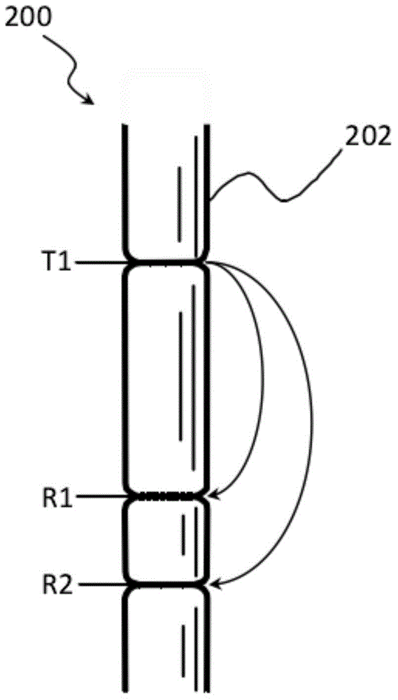
[0008] The purpose of the embodiments of the present invention is to provide a method for measuring the formation resistivity at the drill bit to solve the problem of measurement lag caused by the distance between the drill bit and the traditional propagation logging tool in the related art

Method used


Image

  • Method for measuring formation resistivity at drill place
  • Method for measuring formation resistivity at drill place
  • Method for measuring formation resistivity at drill place

Examples


Embodiment Construction

[0026] Hereinafter, the present invention will be described in detail with reference to the drawings and examples. It should be noted that, in the case of no conflict, the embodiments in the present application and the features in the embodiments can be combined with each other.

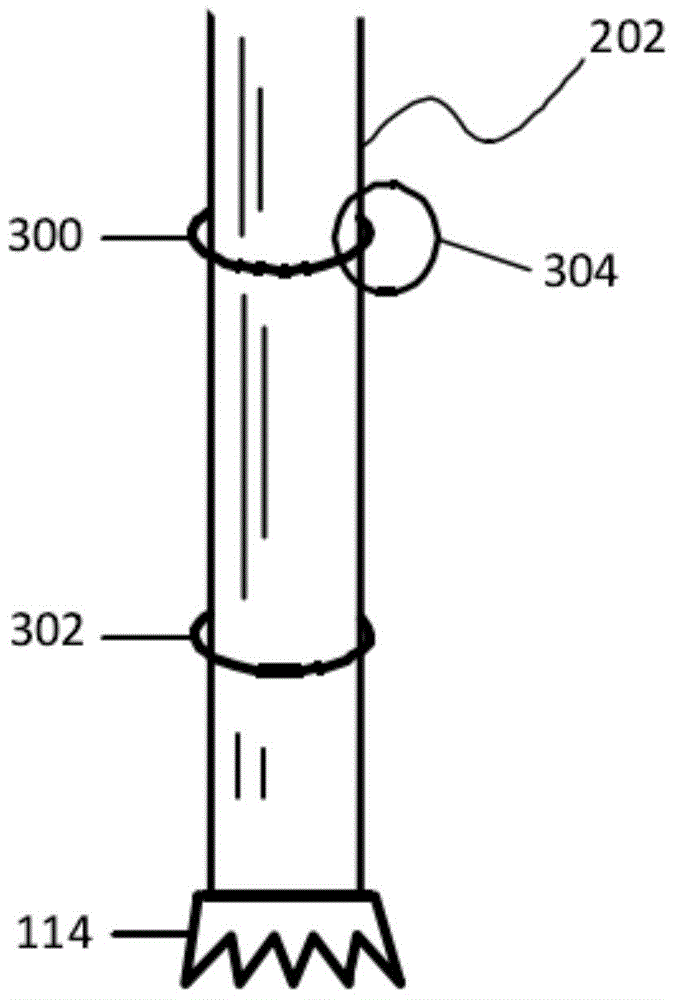
[0027] The embodiment of the present invention also provides a device for measuring the formation resistivity at the drill bit, including:

[0028] a tool housing;

[0029] a transmitter configured on the tool housing;

[0030] a receiver arranged on the tool housing at an axial distance from the transmitter;

[0031] A transmit signal coupler, coupled with the transmitter and receiver antennas.

[0032] The above-mentioned transmitter generates an electric signal, and converts the electric signal into an electromagnetic signal and transmits it into the formation through the transmitting antenna. The receiver measures the amplitude and phase of the electromagnetic signal in the formation. The tr...


PUM


Abstract

The invention discloses a method for measuring formation resistivity at a drill place. The method comprises that a tool housing is placed into a borehole; a transmitter transmits an electromagnetic signal to the stratum; a transmission signal coupler is utilized to measure the amplitude and the phase of an electrical signal generated on antenna of the transmitter; a receiver is utilized to measure the amplitude and the phase of the electromagnetic signal from the transmitter; according to the amplitude and the phase of the electrical signal measured by the transmission signal coupler and the amplitude and the phase of the electromagnetic signal measured by the receiver, the amplitude attenuation and the phase difference are calculated; and according to the amplitude attenuation and the phase difference, the formation resistivity at the drill place is calculated. The method solves a problem of a conventional transmission resistivity logging tool of measurement lag due to the difference between a measuring point position and the drill, and improves the practicability of the equipment.

Description

technical field [0001] The invention relates to the field of resistivity logging, in particular to a method for measuring formation resistivity at a drill bit. Background technique [0002] Gathering downhole information typically uses electrical measurement methods such as logging while drilling (“LWD”), measurement while drilling (“MWD”), and wireline logging systems. Well known in the oil industry, these techniques have long been used to obtain downhole information, for example, using formation resistivity (or conductivity; the terms "resistivity" and "conductivity", although opposite in meaning, are used interchangeably in the art) And various petrophysical models (such as Archie's law) can be used to determine the petrophysical properties of formations and corresponding fluids. In related technologies, resistivity is an important parameter reflecting the oil and gas (such as crude oil or natural gas) and water content in porous formations, so it is best to keep the wel...

Claims


Application Information

Patent Timeline
Patent Type & Authority Applications(China)
IPC IPC(8): E21B49/00
CPCG01V3/28G01V3/12
Inventor 刘乃震赵齐辉卢毓周李永和白锐李敬刘策宋振虎
Owner BC P INC CHINA NAT PETROLEUM CORP
Why Eureka
Eureka Blog
Learn More