System and method for testing performance of fluorescent powder

A test system and fluorescent powder technology, applied in the direction of fluorescence/phosphorescence, material excitation analysis, etc., can solve the problems of complex operation, large test error, high cost, etc., and achieve the effect of simple operation

Active Publication Date: 2014-02-26
NANJING COLLEGE OF INFORMATION TECH
View PDF3 Cites 8 Cited by
  • Summary
  • Abstract
  • Description
  • Claims
  • Application Information

AI Technical Summary

Problems solved by technology

Although this method can directly obtain the application performance of phosphor powder, it also has shortcomings: most of the process of device manufacturing is involved in the test, the operation is complicated, and the cost is high; the material of the device is not consistent with the manufacturing process, and it is difficult to ensure the fluorescence Powders have the same excitation test conditions, affecting test repeatability
Parallel testing of multiple phosphor samples cannot be carried out at the same time, which affects the regularity search and low test efficiency; the distance between the plates cannot be flexibly adjusted, which limits the test function; the light efficiency of this type of phosphor is very low, and its emission After the light is split by a monochromator, etc., the light signal is very weak. Only a photomultiplier tube is used as a conversion device. The background signal is high, which often leads to large test errors.
In addition, in the prior art, the test systems that use electron guns to test FED phosphors and vacuum ultraviolet light sources to test PDP phosphors do not have the multi-purpose function of one machine, and can only undertake their own test tasks.

Method used


Image

  • System and method for testing performance of fluorescent powder
  • System and method for testing performance of fluorescent powder
  • System and method for testing performance of fluorescent powder

Examples


Embodiment Construction

[0057] Further illustrate below in conjunction with accompanying drawing and specific embodiment:

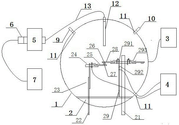
[0058] Such as figure 1 In the specific embodiment shown, the fluorescent powder performance testing device system of the present invention includes a vacuum sample chamber 1, a test platform 2, a vacuum device 3, a high voltage power supply 4, an excitation source, an acquisition optical fiber, a monochromator 5, and a single photon counter 6 and data processor 7 .

[0059] The test platform includes a main support, a cathode support and a sample support. The cathode support includes a cathode support rod 22 and a cathode support plate 24. The cathode support plate 24 is connected to the cathode support rod 22 by a linear guide rail 23 and is installed perpendicular to the cathode support rod 22. FED cathode sheet 25 is installed on the cathode sheet supporting plate 24, has cathode test area 27 on the FED cathode sheet 25; On the sample pallet, the sample piece 28 has a samp...


PUM


Abstract

The invention discloses a system and method for testing the performance of fluorescent powder. The system comprises a vacuum sample chamber, a testing platform, a vacuumizing device, a high-voltage power supply, an excitation source, a collection optical fiber, a monochrometer, a single-photon counter and a data processor, wherein the testing platform comprises a cathode bracket and a sample bracket; an FED (Field Emission Display) cathode piece is arranged on the cathode bracket; a sample piece is arranged on the sample bracket; a sample testing region on the sample piece is located above a cathode testing region of the FED cathode piece; an output end of the high-voltage power supply can be used for respectively outputting a high electric potential and a low electric potential to the cathode piece and the sample piece respectively to realize simulated FED excitation; the excitation source can be a vacuum ultraviolet source or an electronic gun and acts on the sample testing region so that a sample emits light and a light-emitting signal can be collected by the collection optical fiber and is processed by the monochrometer, the single-photon counter and the data processor to obtain performance data related to fluorescent powder to be detected. The system can be applicable to the testing method for the fluorescent powder by adopting various excitation sources, is simple and convenient to operate and high in testing efficiency and precision.

Description

technical field [0001] The invention relates to a performance testing technology of fluorescent powder, in particular to a fluorescent powder performance testing system and a testing method. Background technique [0002] Luminescent properties such as spectral power distribution, relative brightness, color coordinates, and color rendering index of phosphors are key indicators for evaluating the performance of phosphors, and the calculations of relative brightness, color coordinates, and color rendering index are all based on the spectral power distribution of phosphors , therefore, measuring the spectral power distribution is the most important work. [0003] Such ordinary luminescent materials that use ultraviolet light to excite light, such as fluorescent powder for fluorescent lamps, have relatively mature testing techniques. Generally, an ultraviolet light source (such as a mercury lamp with a filter) is used as an excitation source to irradiate the phosphor to emit lig...

Claims


Application Information

Patent Timeline
Patent Type & Authority Applications(China)
IPC IPC(8): G01N21/64
Inventor 朱宪忠孙士祥赵春宝张彦娜曾明敏郭萍赵玮周志近
Owner NANJING COLLEGE OF INFORMATION TECH
Why Eureka
Try Eureka