Control method of all-optical switch

A control method and an all-optical switch technology, applied in the field of optical switches, can solve the problems of complex optical switch technology and low practicability, and achieve the effects of high signal-to-noise ratio, short switching time, and improved performance

Active Publication Date: 2014-03-05
SHANXI UNIV
View PDF5 Cites 10 Cited by
  • Summary
  • Abstract
  • Description
  • Claims
  • Application Information

AI Technical Summary

Problems solved by technology

[0007] The present invention provides an all-optical switch control method in order to solve the tech

Method used


Image

  • Control method of all-optical switch
  • Control method of all-optical switch
  • Control method of all-optical switch

Examples


Embodiment Construction

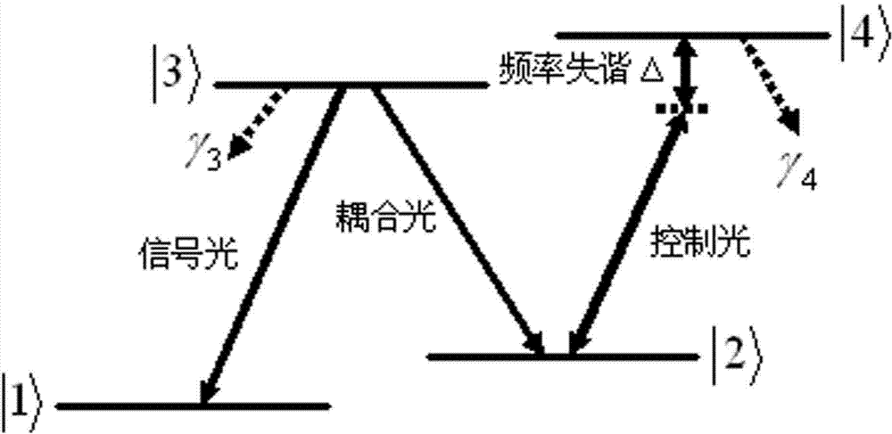
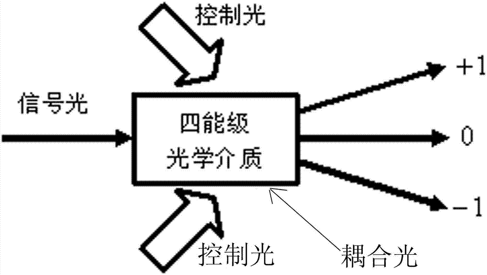
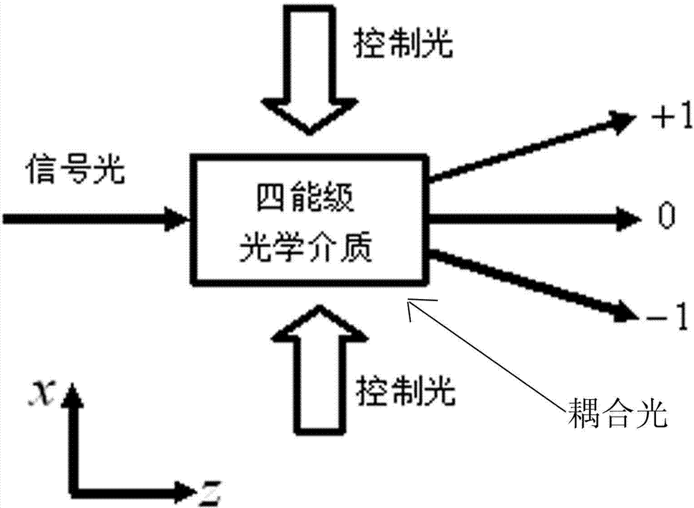
[0023] An all-optical switch control method, comprising the following steps: (a) injecting two beams of control light into a four-level optical medium, and crossing the two beams of control light in the four-level optical medium, forming a standing wave light in the intersection area field; then inject a beam of signal light into the four-level optical medium and pass through the intersection area of ​​two beams of control light; the optical paths of the signal light and control light are not parallel; (b) inject a beam of coupling light into In the four-level optical medium and through the area where the signal light crosses the two beams of control light; the energy levels of the four-level optical medium from low to high are |1>, |2>, |3>, |4 >; where |1> is the ground state, |2> is the metastable state, |3> and |4> are both excited states; the frequency of the input signal light satisfies The resonant transition frequency; control the frequency of light and There is a f...


PUM


Abstract

The invention relates to the field of optical switches, in particular to a control method of an all-optical switch. The technical problem that an existing optical switch is complex in technology and poor in practicability is solved. The control method of the all-optical switch comprises the following steps that (1) two beams of control light enter a four-energy-level optical medium in an incidence mode, and intersect in the four-energy-level optical medium, and one beam of signal light enters the four-energy-level optical medium in an incidence mode, and passes through the region of intersection between the two beams of control light; (2) one beam of coupling light enters the four-energy-level optical medium in an incidence mode, and passes through the region of intersection between the signal light and the two beams of control light; (3) intensity changes of zero-level diffraction light can be achieved by changing the existence state of the control light. According to the control method of the all-optical switch, the control light and the coupling light used in an optical switch system can be weak, and even can be light at the quantum level, energy consumption is greatly reduced, and the all-optical switch can even serve as a quantum all-optical switch device.

Description

technical field [0001] The invention relates to the field of optical switches, in particular to an all-optical switch control method. Background technique [0002] In the traditional optical-electrical-optical backbone network nodes, especially the hub nodes, about 70-80% of the traffic is typically direct, and all of them have to be processed by photoelectric conversion for a small amount of business. The optical signal is converted into an electrical signal, switched and routed, and then converted into an optical signal and sent to the appropriate optical path. This electrical processing technology greatly limits the superiority of wavelength division multiplexing (WDM) technology, making the throughput of network nodes and even the network smaller, forming an "electronic bottleneck". Considering the operation of this current network, in order to further overcome the "electronic bottleneck" phenomenon, an all-optical network has surfaced. All-optical network (AON) refers...

Claims


Application Information

Patent Timeline
IPC IPC(8): G02F1/01
Inventor 董雅宾郭耀华
Owner SHANXI UNIV
Why Eureka
Try Eureka