A vehicle security system based on real-time control vehicle communication network technology
A technology of in-vehicle communication and network technology, applied in the field of automotive security systems, can solve the problems of small alarm range, unindustrialization, and inability to meet the consumer needs of small and medium-sized private-brand car owners, to improve reliability and robustness. sex, promoting prosperity and social stability, and improving the effect of the automotive electronics market
- Summary
- Abstract
- Description
- Claims
- Application Information
AI Technical Summary
Problems solved by technology
Method used
Image
Examples
Embodiment 1
[0036] Embodiment 1 Overall system structure of the present invention
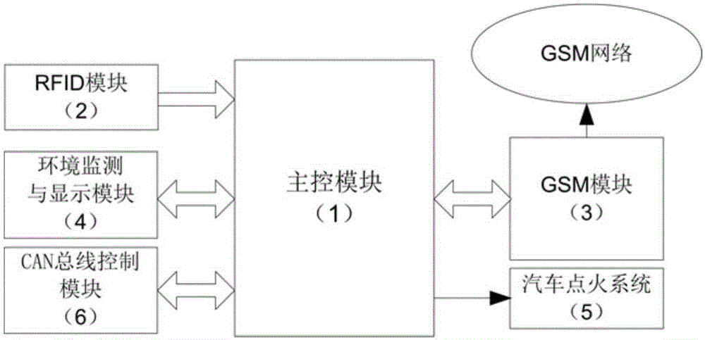
[0037] refer to figure 1 , the structure of the automobile security system based on real-time control vehicle communication network technology of the present invention has, main control module 1, RFID module 2, GSM module 3 and automobile ignition system 5, wherein main control module 1 is responsible for coordinating the work between each module When the radio frequency identification card is brought close to the RFID module 2, the RFID module 2 reads the information in the identification card and sends it to the main control module 1, and the main control module 1 compares the received information with the pre-stored information, and if they are consistent, the car is ignited The ignition module in the system 5 is turned on, and the car can be started normally with the car key at this time. If it is inconsistent, the ignition module is locked so that the car key cannot start the car, and an alarm message...
Embodiment 2
[0038] Embodiment 2 Main control module 1 of the present invention
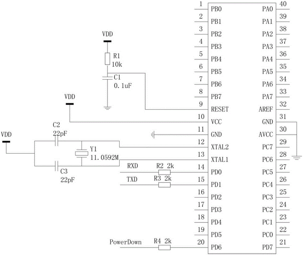
[0039] refer to figure 2 , the structure of the main control module 1 of the present invention is: 11 pins, 30 pins and 31 pins of the single-chip microcomputer Atmega16L are all grounded, 10 pins are connected to the power supply VDD, 9 pins are grounded through the capacitor C1, and the 9 pins are also connected to the power supply VDD through the resistor R1 simultaneously. The crystal oscillator Y1 with a frequency of 11.0592MHz is connected between pin 12 and pin 13. At the same time, pin 12 and pin 13 are connected to the power supply VDD through capacitor C2 and capacitor C3 respectively. Pin 14, pin 15 and pin 20 are respectively connected to resistors R2, R3 and R4. One end, the other end of resistors R2, R3 and R4 are respectively used as the RXD port, TXD port and PowerDown port of the main control module 1, and the pin 2 of the single chip microcomputer Atmega16L is connected to the "control sign...
Embodiment 3
[0040] Embodiment 3 RFID module 2 of the present invention
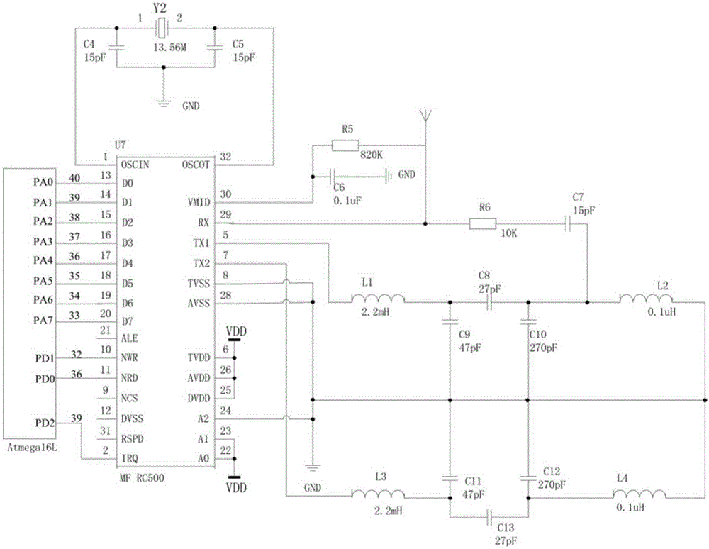
[0041] refer to image 3 , the structure of RFID module 2 of the present invention is: 13,14~20 total 8 pins of chip MFRC500 are connected with total 8 pins of 40,39~33 of single-chip microcomputer Atmega16L in main control module 1 successively, chip MFRC500 Pin 2 is connected to pin 39 of the single-chip microcomputer Atmega16L in the main control module 1, pin 6, pin 22, pin 23, pin 25 and pin 26 of the chip MFRC500 are all connected to the power supply VDD, pin 8, pin 24 and pin 28 are all grounded, and pin 1 The crystal oscillator Y2 with a frequency of 13.56MHz is connected between pin and pin 32. At the same time, pin 1 and pin 32 are grounded through capacitor C4 and capacitor C5 respectively, pin 30 is grounded through capacitor C6, pin 30 is also connected to pin 29 and the antenna through resistor R5 , Connect one end of capacitor C7, the other end of capacitor C7 is grounded through the parallel inductor...
PUM
 Abstract
Description
Claims
Application Information
 - R&D
- Intellectual Property
- Life Sciences
- Materials
- Tech Scout
- Unparalleled Data Quality
- Higher Quality Content
- 60% Fewer Hallucinations
Browse by: Latest US Patents, China's latest patents, Technical Efficacy Thesaurus, Application Domain, Technology Topic, Popular Technical Reports.
© 2025 PatSnap. All rights reserved.Legal|Privacy policy|Modern Slavery Act Transparency Statement|Sitemap|About US| Contact US: help@patsnap.com


