Intelligent drilling television imaging instrument

A technology of drilling TV and imager, which is applied in the direction of construction, etc., can solve the problems affecting the analysis of drilling data, image color distortion, inconvenience, etc., and achieve the effect of avoiding depth counting errors, preventing cable twisting, and facilitating imaging

Inactive Publication Date: 2014-03-12
YUEYANG AOCHENG TECH
View PDF6 Cites 23 Cited by
  • Summary
  • Abstract
  • Description
  • Claims
  • Application Information

AI Technical Summary

Problems solved by technology

However, due to factors such as unreasonable light source design and insufficient light source brightness, fogging of the lens glass protective cover, depth error and inaccurate image splicing caused by manually lowering the probe, the obtained image data is not clear enough. The color of the image is distorted and the image resolution is not enough, which affects the analysis of drilling data and the accuracy of survey results; at the same time, this type of in-hole TV probe does not have both in-hole video and full-hole wall imaging modes, which is difficult for on-site data acquisition. It brings great limitations; in the end, digital data such as images and videos detected by this type of borehole TV imager fail to form an electronic core library, which is not convenient for browsing, archiving, and retrieval of borehole electronic data. inconvenience to researchers

Method used


Image

  • Intelligent drilling television imaging instrument
  • Intelligent drilling television imaging instrument
  • Intelligent drilling television imaging instrument

Examples


Embodiment Construction

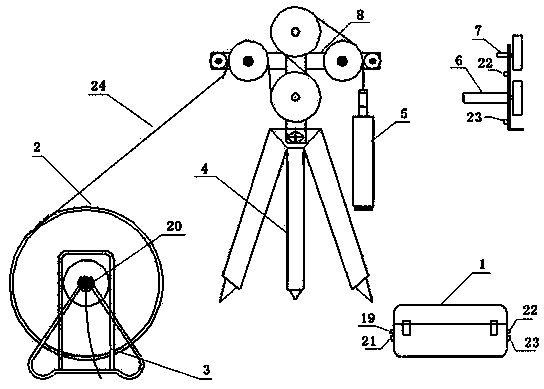
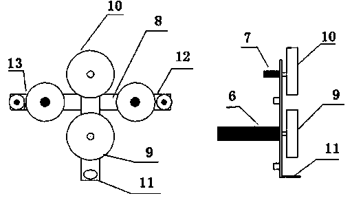
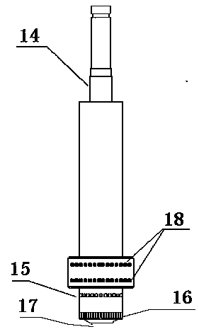
[0016] like figure 1 , figure 2 , image 3 As shown, the present invention mainly consists of main control machine 1, downhole probe 5, downhole cable 24, winch 3, wheel hub 8, stepping motor 6 and motor drive wheel 9, depth counter 7 and depth counting wheel 10, front and rear crimping wheels 13,12 and tripod 4 form.

[0017] Before the system works, place the tripod 4 directly above the drill hole to be tested, connect the downhole probe 5 and the cable tail joint, and lock it (waterproof) with a matching wrench, and the winch cable 2 according to figure 1 The hub 8 is bypassed in the middle winding mode, and the main control machine 1 power interface 21 is connected to the 12V DC power supply; the depth counter interface 22 and the stepping motor interface 23 on the hub 8 are connected to the corresponding interfaces 22 and 23 on the main control machine 1; one end of the winch The interface 20 is connected to the main control computer video interface 19 through the vid...


PUM


Abstract

The invention relates to an intelligent drilling television imaging instrument, which mainly consists of a main controller, an underground probe, an underground cable, a windlass, a hub, a stepper motor, a depth counter and a tripod. The main controller is used for collecting and storing the information such as image splicing, video, depth and azimuth angle; the underground cable is used for supplying power to the probe and transmitting a control order, video, angle and the like; the underground probe is used for shooting a picture and video and recording the underground azimuth angle and transmitting the information to an industrial control computer through the cable; the depth counter is used for recording the underground depth of the underground probe; the stepper motor is used for controlling the probe to ascend and descend at a constant speed. An open-type lens is directly arranged in the water, and no glass cover is arranged in front of the lens, so that a shot image of a well wall is clearer, and the color retention is more authentic; a combined-type light source is adopted, so that the well wall and the underground situation can be directly observed; by adopting the unique stepper motor and the depth counting hub device, the probe can be lowered and lifted at a constant speed, and the images are completely spliced; by introducing electronic rock core library software, an electronic rock core file is established.

Description

technical field [0001] The invention relates to an intelligent borehole TV imager, which belongs to geophysical exploration equipment and is suitable for engineering geology, hydrogeology, geological prospecting, geotechnical engineering, mines and other departments; it is suitable for vertical holes, horizontal holes and inclined holes (depression angle , elevation angle), anchor cable (rod) holes, geological drilling and concrete drilling and other types of drilling. Form digital drilling panorama pictures and videos, and finally summarize them into a digital core library to store the data permanently. The present invention is especially suitable for fracture zone formations where actual rock cores cannot be obtained. It is used for observing the wall conditions in various boreholes and observing various characteristics and fine structures of geological bodies in boreholes, such as stratum lithology, rock structure, and faults. , fissures, interlayers, karst, ore body ore t...

Claims


Application Information

Patent Timeline
Patent Type & Authority Applications(China)
IPC IPC(8): E21B47/002
Inventor 王槐仁徐义贤陈松曹伟良王志敏王浩明
Owner YUEYANG AOCHENG TECH
Why Eureka
Try Eureka