Raman spectrum measurement system

A measurement system and Raman spectroscopy technology, applied in measurement devices, Raman scattering, material analysis by optical means, etc., can solve the problems of increasing the complexity of the preparation process of porous gold substrates, poor repeatability, and increasing costs.

Inactive Publication Date: 2014-03-12
INST OF ELECTRONICS CHINESE ACAD OF SCI +1
View PDF2 Cites 23 Cited by
  • Summary
  • Abstract
  • Description
  • Claims
  • Application Information

AI Technical Summary

Problems solved by technology

However, the existing research results show that the Raman enhancement factor of conventional porous gold substrates under bulk beam irradiation is not high, which is difficult to meet the needs of practical applications. Therefore, scientists have explored various methods to improve the Raman enhancement factor of porous gold: L.H. Qian et al. found that the enhancement factor of porous gold substrates is related to the size of the pores: the smaller the pores, the higher the enhancement factor [Qian L H, Yan X Q, Fujita T, et al.Surface enhanced Raman scattering of nanoporous gold: Smaller pore sizes stronger enhancements.Applied physics letters, 2007, 90(15): 153120(1-3)]; Yang Jiao et al processed a two-dimensional periodic structure on the porous gold surface by nanoimprinting technology, increasing the enhancement factor to 10 7 Above [Jiao Y, Ryckman J D, Ciesielski P N, et al. Patterned nanoporous gold as an effective SERS template, Nanotechnology, 2011, 22(29): 295302.]; Hongwen Liu and Ling Zhang immobilized porous gold on prestressed polymer , and then annealed it, ...

Method used


Image

  • Raman spectrum measurement system
  • Raman spectrum measurement system
  • Raman spectrum measurement system

Examples


Embodiment Construction

[0036] In order to make the object, technical solution and advantages of the present invention clearer, the present invention will be described in further detail below in conjunction with specific embodiments and with reference to the accompanying drawings. It should be noted that, in the drawings or descriptions of the specification, similar or identical parts all use the same figure numbers. Implementations not shown or described in the accompanying drawings are forms known to those of ordinary skill in the art. In addition, the directional terms mentioned in the following embodiments, such as "upper", "lower", "front", "rear", "left", "right", etc., are only referring to the directions of the drawings. Accordingly, the directional terms are used to illustrate and not to limit the invention.

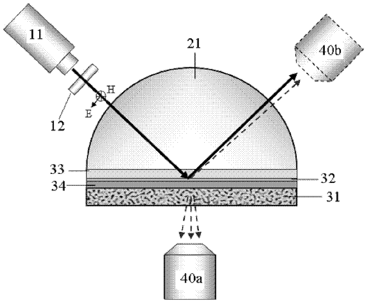
[0037] The Raman spectroscopy measurement system of the present invention comprises: a linearly polarized laser light source 10; a total reflection element 20, located on one side of ...


PUM


Abstract

The invention provides a Raman spectrum measurement system. The Raman spectrum measurement system comprises a linear polarization laser source, a total reflection element located at one side of the linear polarization laser source, a porous metallic film directly or indirectly clinging to the total reflection element and a Raman probe, wherein an interface of the total reflection element and the porous metallic film is used as a total reflection surface. The linear polarization laser source generates linear polarization laser beams with a magnetic field vibration direction parallel to the total reflection surface; the laser beams enter into the total reflection element and undergo total reflection on the total reflection surface; a transverse magnetic polarization evanescent field generated after total reflection excites resonance of surface plasma of the porous metallic film, which leads to reinforcement of a magnetic field at the inner/external surface of the porous metallic film; the reinforced magnetic field excites a Raman signal of the molecule of a to-be-measured object located on the inner/external surface of the porous metallic film; and the Raman signal is detected by the Raman probe. The Raman spectrum measurement system provided by the invention can substantially improve a Raman enhancement factor of the porous metallic film only by adjusting the polarization state of incident light and allowing the incident light to be in a transverse magnetic polarization state.

Description

technical field [0001] The invention relates to the technical field of molecular spectrum detection, in particular to a Raman spectrum measurement system. Background technique [0002] Raman spectroscopy is mainly used to measure molecular vibration and rotational spectrum, and then obtain information such as material composition, structure and content. At present, Raman spectroscopy has been widely used in environmental monitoring, food safety testing, public and national defense security testing, judicial identification, jewelry identification, material analysis, biology and medicine. [0003] The biggest problem encountered in the application of Raman spectroscopy is that the Raman scattering cross section of molecules is very small, making the Raman signal extremely weak and difficult to be detected. For this reason, various methods have been invented to enhance Raman signals, including: Surface Enhanced Raman Detection (SERS), Electron Resonance Enhanced Raman Detectio...

Claims


Application Information

Patent Timeline
IPC IPC(8): G01N21/01G01N21/65
CPCG01N21/658
Inventor 祁志美陈晨逯丹凤田中群
Owner INST OF ELECTRONICS CHINESE ACAD OF SCI
Why Eureka
Try Eureka