
Automatic testing method for electromagnetic transmissivity

An automatic test and wave transmittance technology, which is applied to measuring devices, material analysis by means of microwaves, instruments, etc., can solve the problems of large manpower and time, relatively harsh electromagnetic environment requirements of the test site, and low efficiency, and achieve suppression Effects of multi-path interference, improving test efficiency, and saving human resources

Inactive Publication Date: 2014-03-12
THE 41ST INST OF CHINA ELECTRONICS TECH GRP
View PDF4 Cites 7 Cited by
  • Summary
  • Abstract
  • Description
  • Claims
  • Application Information

AI Technical Summary

Problems solved by technology

[0017] The signal source + spectrum analyzer method can only perform single-frequency point testing. If broadband testing is required, this method will consume a lot of manpower and time;
[0018] The scalar network analyzer method can be used for broadband sweep measurement, but the disadvantage is that it is difficult to effectively suppress the impact of multipath interference on the test, and the electromagnetic environment requirements of the test site are relatively strict;
[0019] The vector network analyzer method can be used for broadband sweep measurement, and the influence of multipath interference on the test can be effectively reduced by setting the time domain gate, but manual operation of the instrument is required, and the efficiency is low
[0020] The above three methods can measure the electromagnetic transmittance of materials, but they all have certain disadvantages, and can only measure the transmittance of electromagnetic waves under a certain polarization mode, and it is difficult to meet the complex electromagnetic environment of the modern battlefield. Test requirements for electromagnetic properties of materials

Method used


Image

  • Automatic testing method for electromagnetic transmissivity

Examples


Embodiment 1

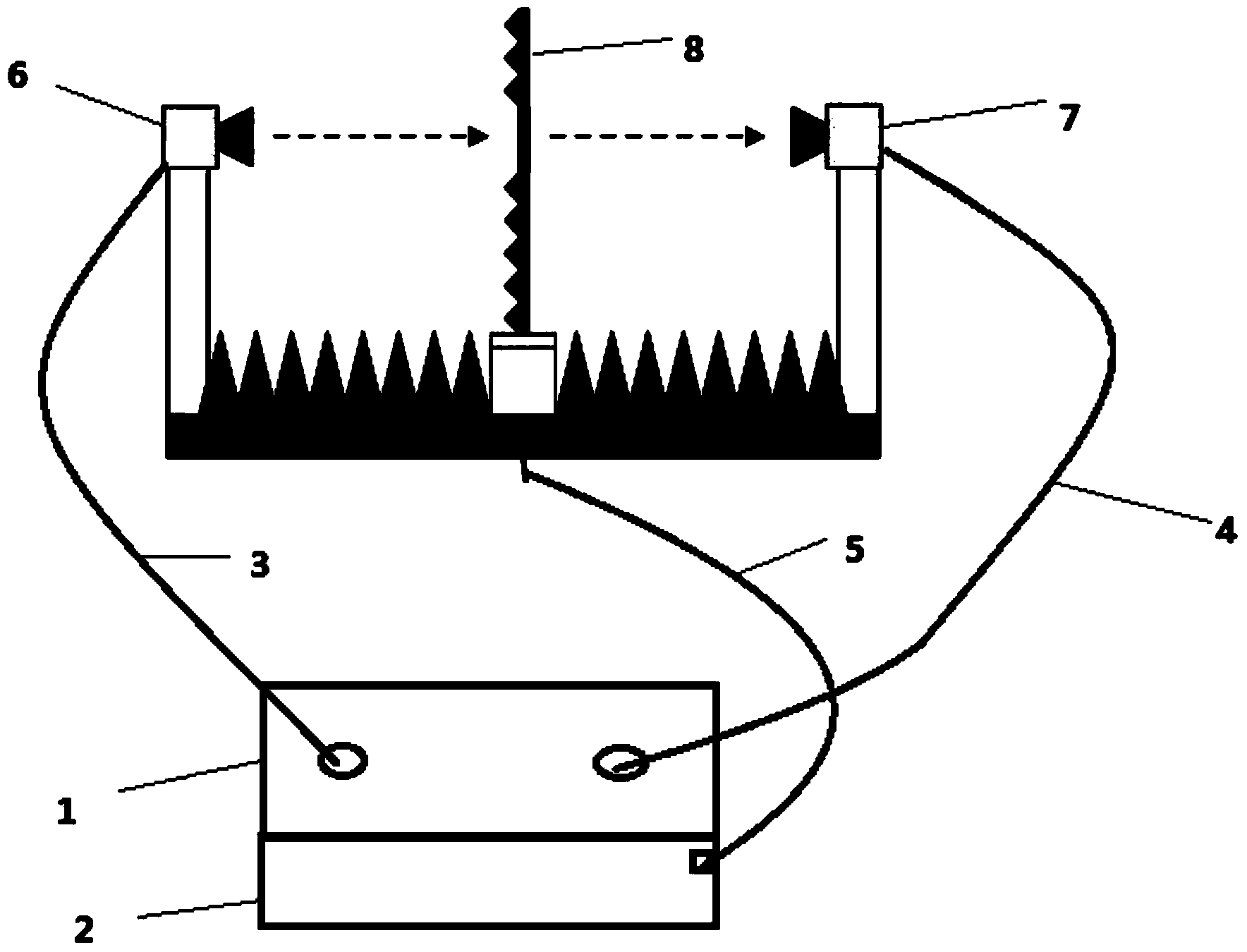
[0043] The realization principle of the electromagnetic wave transmittance automatic test system proposed by the present invention is as follows: figure 1 As shown, it includes a vector network analyzer 1, a test cable, test antennas 6 and 7, and a wave transmittance test device 8.

[0044] The vector network analyzer is the main test instrument in the system, with frequency domain measurement and time domain gating functions. The test instrument is connected to the transmitting antenna through a microwave test cable to complete the generation and transmission of the excitation signal; it is connected to the receiving antenna through a microwave test cable to complete the reception and processing of the excitation signal.

[0045]The wave transmittance testing device is the key equipment to realize automatic measurement. The device includes four parts: the main frame, the polarization rotation unit, the azimuth rotation unit, and the drive assembly. The main frame is in the s...


PUM


Abstract

The invention provides an automatic testing method for electromagnetic transmissivity, which is based on an automatic control theory and comprises the steps as follows: a polarization rotation module of a testing device is controlled via computer programs, so that a signal transmitting device and a signal receiving device can synchronously rotate; a control direction rotation module enables a sample to be tested to rotate to an appointed direction; tested frequency-domain data is automatically converted into time-domain data, the position of a time-domain gate is calculated, and the opening / closing of the time-domain gate is automatically controlled. According to the invention, with the adoption of the scheme, the automatic regulation of an electromagnetic wave polarization manner and an incidence angle is achieved, and the automatic control of a time-domain strobing function is realized, so that the automatic test to automatic calibration and electromagnetic transmissivity is achieved in different polarization manners and at multiple incidence angles. The automatic testing method for the electromagnetic transmissivity improves the accuracy of the degree of automation and test results during testing, saves manpower and boosts testing efficiency.

Description

technical field [0001] The invention belongs to the technical field of wave transmittance testing, and in particular relates to an automatic testing method for electromagnetic wave transmittance. Background technique [0002] The electromagnetic transmittance of a material refers to the ratio of the power of the electromagnetic wave through the material plate to the power of the electromagnetic wave through the free space under the same conditions, which is an important characterization parameter of the electromagnetic properties of the material. The test of electromagnetic transmittance has become more and more important with the extensive use of dielectric materials in microwave communication, satellite communication, missile guidance, electronic countermeasures, radar navigation and other fields. [0003] The basic test method of electromagnetic wave transmittance is: the signal transmitting and receiving equipment are respectively connected to the transmitting antenna an...

Claims


Application Information

Patent Timeline
IPC IPC(8): G01N22/00
Inventor 殷志军赵锐唐敬双张文涛金羲宸
Owner THE 41ST INST OF CHINA ELECTRONICS TECH GRP
Learn More