Anti-creeping method for electrochemical facility containing flowing electrolyte and anti-creeper
A flowing electrolyte, electrochemical technology, applied in electrochemical generators, fuel cell parts, circuits, etc., can solve problems such as leakage, voltage drop, short-circuit current generation, etc., to save copper, improve energy density and Power density, effect of reducing flow resistance
- Summary
- Abstract
- Description
- Claims
- Application Information
AI Technical Summary
Problems solved by technology
Method used
Image

Examples
Embodiment 1
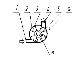
[0057] See Figure 3A , Figure 3B , Figure 3C , Install a partition impeller G in the inlet and outlet channels respectively, the partition impeller G includes a shell 2, a hub 6, a plurality of partition blades 3, an impeller shaft 5, 8 partition blades 3 are arranged at intervals on the hub 6 on. The electrolyte flowing into the partition impeller G impacts the partition blade 3 to rotate, and the electrolyte is separated on both sides of the impeller blade 3. The partition blade 3 is made of insulating material, and the insulating material is nylon. The current in the liquid flow is connected and conducted. Therefore, it is disconnected, thus eliminating the short circuit and leakage caused by the continuous flow of electrolyte. Figure 3A , Figure 3B , Figure 3C It is a corner partition impeller, Figure 3D It is a straight-through partition impeller.
[0058] See Figure 5 , There are partitioned impellers 2 and 5 near the A electrolyte inlet 1 and A electrolyte outlet ...
Embodiment 2
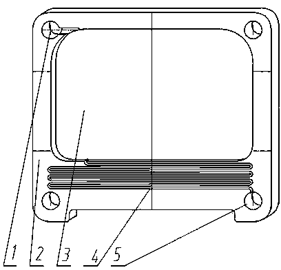
[0060] See Figure 4A , Figure 4B with Figure 4C The valve isolation device includes an elastic housing 3, upper and lower valves 4, 2, electrolyte inflow and outflow branch pipes 1, 5, and an extrusion device. The extrusion device is not shown in the figure, and the electrolyte flows in , Outflow branch pipes 1, 5 are respectively located at the lower end and upper end of the elastic shell, the upper and lower valves 4, 2 are respectively located at the lower inlet and the upper outlet of the elastic shell 3. The upper valve 4 and the lower valve 2 are The elastic rubber body is partly connected with the elastic shell 3, and partly can be switched. The squeezing device has an squeezing ring and a controller, the squeezing ring is sleeved outside the elastic shell, the controller receives a pulse voltage, and when the pulse voltage is high, the squeezing ring squeezes the elastic shell inward , The lower valve 2 is closed and the upper valve 4 is opened. When the pulse voltag...
Embodiment 3
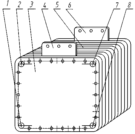
[0064] See Figure 6A , Figure 6B with Figure 6C For large and medium-sized liquid flow battery panels, it is also possible to install partition impellers 2, 14 in the liquid inlet and outlet liquid pipes respectively, or use larger diameter electrolyte outflow headers 3, 13 at the liquid outlet. , And make the upper branch pipe into a corrugated pipe, and install it vertically, so that the outflowing electrolyte is disconnected when it falls to the corrugated place freely; deliberately use a larger diameter electrolyte to flow out of the main pipes 3, 13, and let it flow out of the main pipes 3, 13 The upper chamber is always half empty, so that the electrolyte in the outlet branch pipe can only fall to the liquid level of the main pipe, so that the flow of the outgoing electrolyte is disconnected and the electrical conduction is completely disconnected, thus preventing the continuous electrolyte Open circuit and leakage caused by flow. The diameter of the electrolyte outflo...
PUM
 Abstract
Description
Claims
Application Information
 - Generate Ideas
- Intellectual Property
- Life Sciences
- Materials
- Tech Scout
- Unparalleled Data Quality
- Higher Quality Content
- 60% Fewer Hallucinations
Browse by: Latest US Patents, China's latest patents, Technical Efficacy Thesaurus, Application Domain, Technology Topic, Popular Technical Reports.
© 2025 PatSnap. All rights reserved.Legal|Privacy policy|Modern Slavery Act Transparency Statement|Sitemap|About US| Contact US: help@patsnap.com