Numerical control right-angle plate shearing machine

A shearing machine, right-angle technology, applied in the direction of shearing machine equipment, shearing device, metal processing equipment, etc., can solve the problems of affecting shearing accuracy, large lateral force, thermal energy loss, etc., to improve operation stability, up and down The effect of smooth movement and long service life

Active Publication Date: 2014-03-19
JIANGSU YAWEI MACHINE TOOL
View PDF5 Cites 1 Cited by
  • Summary
  • Abstract
  • Description
  • Claims
  • Application Information

AI Technical Summary

Problems solved by technology

Its obvious disadvantages are: the device needs to be equipped with a hydraulic oil cooling system, and the leakage of hydraulic oil and the treatment of waste oil will cause certain environmental pollution. In addition, when working, the oil pump in the hydraulic pump station is continuously working, which will produce A large amount of heat energy is lost, and the shearing machine also consumes electricity when it is not cutting, and will also generate a large amount of energy consumption
Its obvious disadvantage is that in this device, the motor is always in working condition, and the energy consumption is relatively high.
However, when the right-angle shear is performing right-angle cutting, the knife holder will generate relatively large lateral forces in two directions, which will cause the knife holder to have a tendency to ...

Method used


Image

  • Numerical control right-angle plate shearing machine
  • Numerical control right-angle plate shearing machine
  • Numerical control right-angle plate shearing machine

Examples


Embodiment Construction

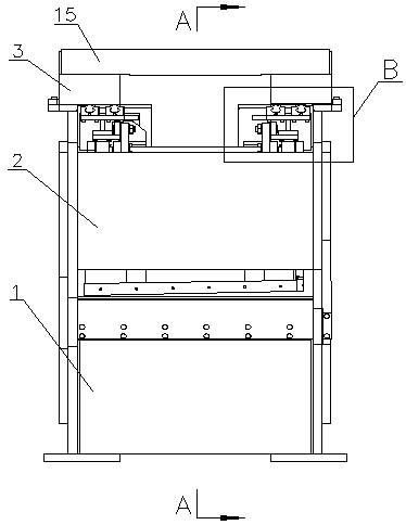
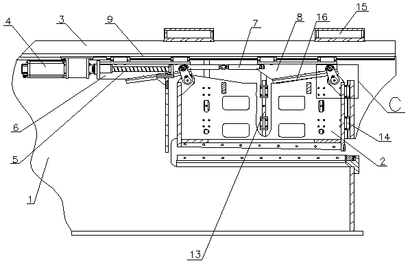
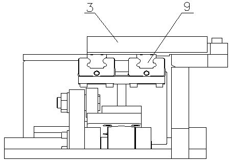
[0023] A four-point pressure servo main transmission mechanism of a numerically controlled right-angle shearing machine, comprising a fuselage 1 and an upper tool rest 2, a crossbeam 3 is arranged symmetrically on the top of the fuselage 1, a servo motor 4 is arranged below the crossbeam 3, and the servo motor The output shaft of 4 is connected with the ball screw 5 through a coupling, and the rear end of the ball screw 5 is sleeved with a main drive wedge 6, and the front end of the main drive wedge 6 is connected with the slave drive wedge 8 through a connecting rod 7. The upper ends of the main transmission wedge 6 and the slave transmission wedge 8 are connected to the ball linear guide rail 19 installed below the crossbeam 3. The lower ends of the main transmission wedge 6 and the slave transmission wedge 8 are provided with a transmission plate 16, and the lower end surface of the transmission plate 16 is Inclined surface, the front end of the inclined surface is higher t...


PUM


Abstract

The invention relates to a numerical control right-angle plate shearing machine. The numerical control right-angle plate shearing machine comprises a machine body (1) and an upper knife carrier (2). At least four driving mechanisms used for driving the upper knife carrier (2) to make vertical motion are arranged above the upper knife carrier (2), and the resultant moment of longitudinal component force applied to the upper knife carrier (2) by all the driving mechanisms is zero. According to the numerical control right-angle plate shearing machine, two servo motors are used for controlling four force bearing points to operate precisely and synchronously, the lateral force generated in the shearing process is not completely borne by a ball linear guide rail on the side face of the upper knife carrier any more, meanwhile, three driving points are further placed over shearing loads, most of the shearing loads can be borne, the tilting moment generated at the center of the upper knife carrier by the shearing loads is basically offset, the influence of stress deformation of the ball linear guide rail due to working loads in operating of the upper knife carrier is greatly reduced, operation is more steady, and shearing precision is also improved; meanwhile, due to the fact that all transmission structures are in a rolling friction mode, energy loss is lower.

Description

technical field [0001] The invention relates to a plate shearing machine, in particular to a four-point pressure servo main transmission mechanism of a numerically controlled right-angle plate shearing machine. Background technique [0002] The right-angle shearing machine is a machine tool that has two blades that are at right angles to each other and can cut the sheet metal at right angles. The CNC right-angle shearing machine can be combined with a CNC punching machine to form a CNC punching and shearing compound machine, which can complete the punching and shearing processes of the plate at the same time. It is a high-efficiency flexible production line. [0003] The main transmission structure of the CNC right-angle shearing machine mainly has the following forms. One is the hydraulic type, which mainly includes a hydraulic pump station. The hydraulic pump station is connected to the hydraulic cylinder through the valve group and the oil pipe. The cylinder body of the h...

Claims


Application Information

Patent Timeline
IPC IPC(8): B23D15/12
Inventor 肖军黄伟徐晓彬
Owner JIANGSU YAWEI MACHINE TOOL
Why Eureka
Try Eureka