Manufacturing method of steel structure box girder

A manufacturing method and technology for steel structures, applied in manufacturing tools, arc welding equipment, welding equipment, etc., can solve problems such as increasing product manufacturing costs, affecting on-site assembly work efficiency, and non-vertical connecting components, saving costs, improving promotion and The value of the application, the effect of saving the site

Active Publication Date: 2014-03-19
GUIZHOU LIHONG STEEL STRUCTURE
View PDF5 Cites 23 Cited by
  • Summary
  • Abstract
  • Description
  • Claims
  • Application Information

AI Technical Summary

Problems solved by technology

[0003] Due to the large size of the components of the steel structure box girder and the large number of bolts, the assembly construction is difficult, time-consuming and laborious, which seriously affects the efficiency of on-site assembly
Since electroslag welding needs to be surrounded by two baffles, partitions and the four side walls of the box-shaped beam / column to form a sleeve shape, and the clearance requirements for the sleeve are very strict, and two thicker baffles are required , also requires low production efficiency and expensive electroslag welding equipment and special nozzles, which is easy to delay the construction period, not only increases the manufacturing cost of the product, but also is difficult, making the production efficiency low
In addition, when the thickness of the wall plate of the beam and column is below 18mm, it is not easy to weld with the current electroslag welding
Since the components are easily deformed during welding, the contact surfaces will not fit together, which will easily cause problems such as non-perpendicularity between the connected components and unqualified flatness, which will cause difficulties in subsequent construction, and once the problem is formed, it is difficult to repair and compensate

Method used


Image

  • Manufacturing method of steel structure box girder
  • Manufacturing method of steel structure box girder
  • Manufacturing method of steel structure box girder

Examples


Embodiment 1

[0029] A method for manufacturing a steel structure box girder, comprising the following steps:

[0030] (1) Use the computer to control the size of the cover plate, web plate and its lining plate, partition plate and its lining plate for blanking, read the data of each component of the steel structure box girder on the AUTOCAD platform, and input it into the CNC flame cutting machine to cut;

[0031] At the same time, make grooves on both sides of the web. The grooves are opened along the thickness direction of the web. The groove angle is 28°, and the groove depth is 1 / 3 of the plate thickness. Make a bevel with an angle of 26°, the bevel depth is the same as the web bevel depth, and drill a hole in the center of the diaphragm;

[0032](2) Assemble the spot-welded liners on the back of the groove of the web and the diaphragm, first adjust and align the quick-fit male joints set on the web and the diaphragm with the corresponding quick-fit female joints set on the spot-welde...

Embodiment 2

[0047] A method for manufacturing a steel structure box girder, comprising the following steps:

[0048] (1) Use the computer to control the size of the cover plate, web plate and its lining plate, partition plate and its lining plate for blanking, read the data of each component of the steel structure box girder on the AUTOCAD platform, and input it into the CNC flame cutting machine to cut;

[0049] At the same time, make grooves on both sides of the web, the grooves are opened along the thickness direction of the web, the groove angle is 30°, the groove depth is 1 / 3 of the plate thickness, and a certain amount of blunt edges are reserved. Make a bevel with an angle of 28°, the bevel depth is the same as the web bevel depth, and drill a hole in the center of the diaphragm;

[0050] (2) Assemble the spot-welded liners on the back of the groove of the web and the diaphragm, first adjust and align the quick-fit male joints set on the web and the diaphragm with the correspondin...

Embodiment 3

[0064] A method for manufacturing a steel structure box girder, comprising the following steps:

[0065] (1) Use the computer to control the size of the cover plate, web plate and its lining plate, partition plate and its lining plate for blanking, read the data of each component of the steel structure box girder on the AUTOCAD platform, and input it into the CNC flame cutting machine to cut;

[0066] At the same time, make grooves on both sides of the web, the grooves are opened along the thickness direction of the web, the groove angle is 32°, the groove depth is 1 / 3 of the plate thickness, and a certain amount of blunt edges are reserved. Beveling, the angle is 30°, the depth of the groove is the same as that of the web, and a hole is drilled in the center of the diaphragm;

[0067] (2) Assemble the spot-welded liners on the back of the groove of the web and the partition, first adjust and align the quick-fit male joints set on the web and the partition with the correspond...


PUM


Abstract

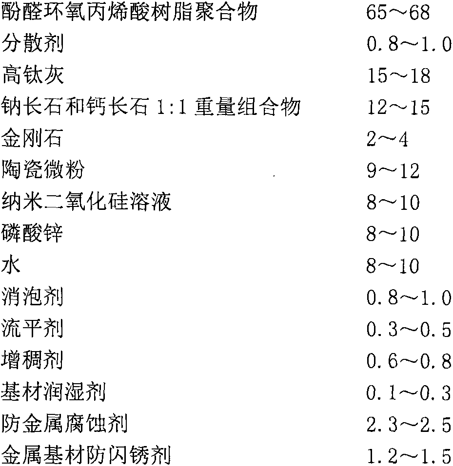
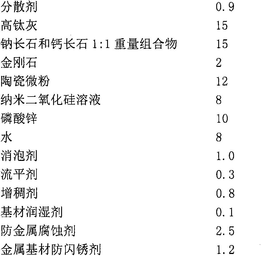
A manufacturing method of a steel structure box girder comprises steps as follows: 1), a computer is used for controlling sizes of a cover plate, webs, lining plates of the webs, a baffle and a lining plate of the baffle for blanking; 2), spot welding lining plates are assembled on back surfaces of grooves of the webs and the baffle respectively; 3), a bottom plate and the two webs are assembled into a U shape and welded on a box girder mould; 4), the baffle is placed and welded in a U-shaped groove; 5), the cover plate is assembled and welded on the U-shaped groove; and 6), the steel box girder is subjected to shot blasting and paint spraying, and paint adopts anticorrosive paint and comprises a component A and a component B. According to the steel structure box girder manufactured with the method, materials are saved, the production efficiency is improved, the integrally formed anticorrosive paint is corrosion-resistant and wear-resistant, and the requirement for inner wall coating of the steel structure box girder is met.

Description

technical field [0001] The invention relates to the field of building steel structures, in particular to a manufacturing method of a steel structure box girder. Background technique [0002] At present, the manufacturing process of the steel structure box girder is roughly as follows: firstly, the column plate is cut with a CNC flame cutting machine, the cover plate, web plate, partition plate and baffle are cut, and the web and partition plate are beveled , the groove opening method is carbon arc gouging cutting V-shaped or K-shaped grooves, and the diaphragm is in the form of single-sided grooves and baffles around. The contact surfaces of the plates, webs and partitions need to be processed, and the baffles to be used are thicker. After the blanking is completed, straightening and correction are carried out. In order to ensure the accurate assembly of the column body, an assembly membrane needs to be prepared. The assembly sequence It is as follows: firstly, the above co...

Claims


Application Information

Patent Timeline
Patent Type & Authority Applications(China)
IPC IPC(8): B23P15/00
CPCB23K9/18B23P15/00
Inventor 焦跃华
Owner GUIZHOU LIHONG STEEL STRUCTURE
Why Eureka
Try Eureka