Devices, kits and detection methods for detecting analytes

A technology for analytes and complexes, applied in measurement devices, analytical materials, material analysis using sonic/ultrasonic/infrasonic waves, etc., and can solve problems such as interference signal measurement

Inactive Publication Date: 2016-03-16
PSYROS DIAGNOSTICS LTD
View PDF12 Cites 0 Cited by
  • Summary
  • Abstract
  • Description
  • Claims
  • Application Information

AI Technical Summary

Problems solved by technology

Besides that, since the systems described in WO90/13017 and WO2004/090512 measure labeled reagents in relation to the sensor surface, u...

Method used


Image

  • Devices, kits and detection methods for detecting analytes
  • Devices, kits and detection methods for detecting analytes
  • Devices, kits and detection methods for detecting analytes

Examples


example 1

[0095] PVDF film

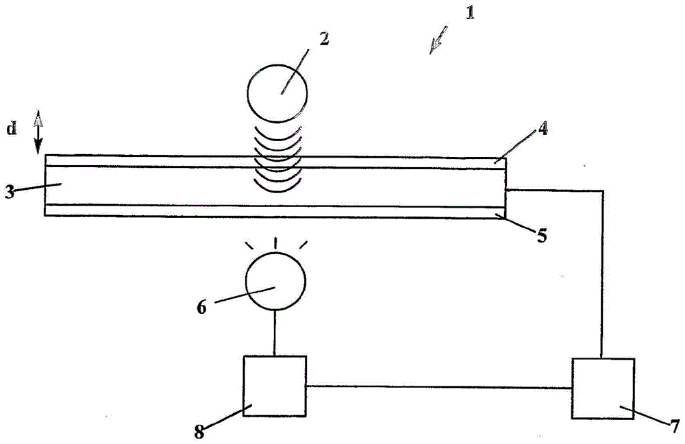
[0096] In the following examples, polarized piezoelectric / pyroelectric polyvinylidene fluoride (PVDF) bimorph films coated with indium tin oxide were used as sensing devices. The ITO surface is coated with a layer of parylene (approximately 1 micron thick) through a vapor phase gas deposition process. This method involves the sublimation and subsequent pyrolysis of cycloarane precursors, followed by free-radical polymerization on the surface. See WO2009 / 141637 for further details. Then, by overnight incubation at room temperature, the resulting film was coated in a streptavidin solution (200 μg / mL-10 mmol / L phosphate buffer containing 2.7 mmol / L KCl, 137 mmol / L NaCl and 0.05% polysorbate). Streptavidin was prepared as described by Tischer et al. (US 5,061,640).

example 2

[0098] Material

[0099] Monoclonal antibodies are produced essentially as described in "Monoclonal Antibodies: Properties, Manufacturing and Applications" by J.R. Birch and E.S. Lennox, Wiley-Blackwell, 1995, and are biotinylated by methods well known in the art. Carbon-labeled reporter conjugates were prepared essentially as described by VanDoorn et al. (US 5,641,689).

example 3

[0101] Preparation of the cartridge

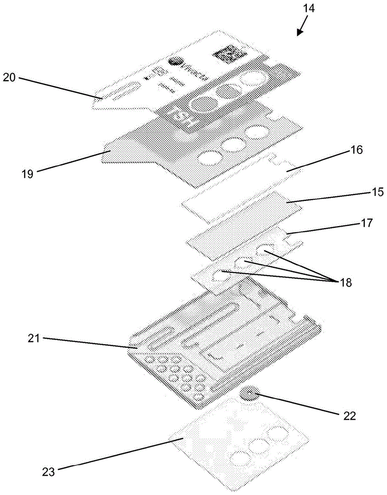
[0102] Such as image 3 As shown in , a cassette 14 was fabricated to perform the assay. The cassette 14 is made of an antibody-coated piezoelectric / pyroelectric film 15 supported on a reinforcement 16 . A polyester film 17 coated with pressure sensitive adhesive, which is die cut to form three sample chambers 18, is applied to the surface. Provisions allow electrical connection to the upper and lower surfaces of the piezoelectric / pyroelectric film 15 to detect the generated charges. The cassette 14 is then formed by sandwiching the above assembly between the top cover 19 and the core 21 coated with the marker 20 , the sealant 22 and the bottom cover 23 .

[0103] Assays are performed by loading the sample chamber with sample using capillary channels in the core 21 . The piezo / pyroelectric film 15 is illuminated through a hole in the top cover 19 with continuous chopped LED light from the LED. For each LED pulse, the voltage across th...


PUM

PropertyMeasurementUnit
Diameteraaaaaaaaaa

Abstract

This invention relates to a device for detecting an analyte in a sample comprising: a radiation source adapted to generate a series of pulses of electromagnetic radiation; a transducer having a pyroelectric or piezoelectric element and electrodes which is capable of transducing energy generated by non-radiative decay into an electrical signal; a detector which is capable of detecting the electrical signal generated by the transducer; a first reagent proximal to the transducer, the first reagent having a binding site which is capable of binding a labelled reagent proportionally to the concentration of the analyte in the sample, which labelled reagent being capable of absorbing the electromagnetic radiation generated by the radiation source to generate energy by non-radiative decay; a second reagent proximal to the transducer, the second reagent having a lower affinity for the labelled reagent under the conditions of the assay than the first reagent; and a third reagent proximal to the transducer, the third reagent having a binding site which is capable of binding the labelled reagent, wherein the third reagent has an affinity for the labelled reagent which is less influenced than the first reagent by the concentration of the analyte or the complex or derivative of the analyte.

Description

technical field [0001] The present invention relates to a device for detecting an analyte, and in particular, to improving the accuracy and precision of devices comprising piezoelectric / pyroelectric transducers. Background technique [0002] Monitoring analytes in solution, such as bioassays of important biological compounds, has wide applicability. Accordingly, a wide variety of analytical and diagnostic devices are available. [0003] WO 90 / 13017 discloses strip-shaped pyroelectric or other thermoelectric transducer elements. Thin film electrodes are disposed on the transducer surface, and one or more reagents are deposited on the transducer surface. When the reagent comes into contact with the species to be detected, a selective colorimetric change occurs. The device will then typically be inserted into a detector where the transducer is illuminated, typically by an LED light source through the transducer, and light absorption by the reagent is detected as microscopic ...

Claims


Application Information

Patent Timeline
IPC IPC(8): G01N21/17G01N29/24G01N33/542G01N33/543
CPCG01N33/54373G01N21/171G01N21/6428G01N29/022G01N33/5302G01N33/542G01N33/582G01N2021/6439G01N2201/062G01N2291/02433G01N2291/0255G01N2291/0256
Inventor 史蒂文·罗斯朱莉·理查兹蒂姆·卡特
Owner PSYROS DIAGNOSTICS LTD
Why Eureka
Try Eureka