Retractable rope used for elevator

A technology for ropes and elevators, applied in the field of stretched ropes for elevators, can solve the problems of no change in the flexibility of the carrier, easy torsion of the traction rope, and reduced service life, and achieve good bending fatigue resistance, uniform force, and improved The effect of longevity

Active Publication Date: 2014-03-26
YUNGTAY ELEVATOR EQUIP CHINA
View PDF11 Cites 14 Cited by
  • Summary
  • Abstract
  • Description
  • Claims
  • Application Information

AI Technical Summary

Problems solved by technology

Since this patent still adopts the intertwisting structure of rope strands, although it can reduce the rope diameter ratio to the traction sheave while ensuring the service life, thereby reducing the diameter of the traction sheave, the flexibility of the carrier itself does not change, so it allows traction. The reduction of pulley diameter is significantly differen

Method used


Image

  • Retractable rope used for elevator
  • Retractable rope used for elevator
  • Retractable rope used for elevator

Examples


Embodiment 1

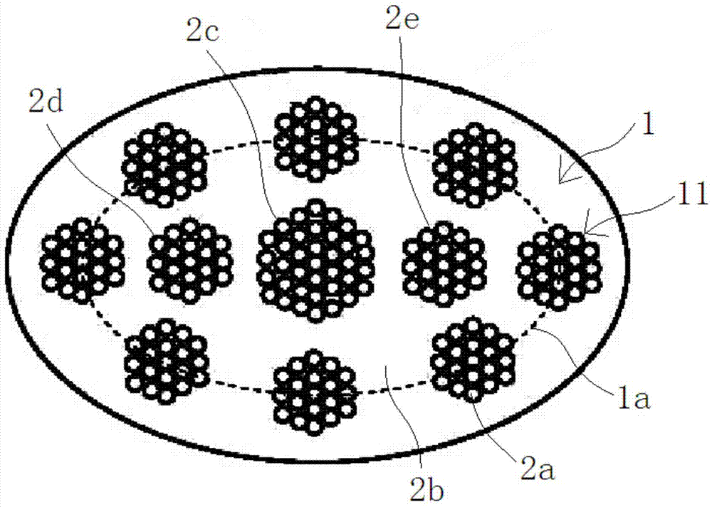
[0052] Such as figure 1 As shown, the elevator tensile rope shown in the figure is composed of a covering layer 1 and 11 bearing bodies. The cross section of the tension rope is designed with an ellipse shape, and the minor axis of the ellipse is perpendicular to the length direction of the tension rope. The outer peripheral surface of the tensile rope forms an outer ellipse 1a, and the ratio r of the major axis to the minor axis of the outer ellipse 1a should not be too large, and the reasonable range is 1≤r≤2. The ratio between the focal length of the outer ellipse 1a and the major axis is 1.618.

[0053] The covering layer 1 is made of non-metallic elastomer material, specifically made of thermoplastic polyurethane rubber. The polyurethane elastomer material is filled between the load-bearing core wires and is wrapped around the periphery of the tensile rope. During the operation of the elevator, the tensile rope bends when passing through the traction sheave. Due to the dif...

Embodiment 2

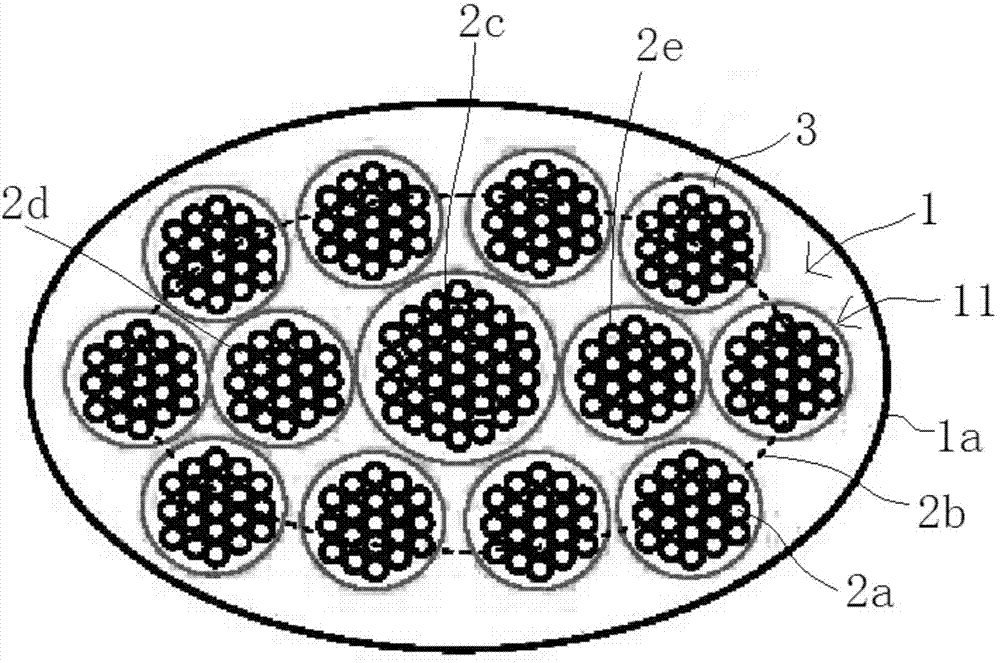
[0060] Such as figure 2 As shown, the difference between the elevator tensile rope of this embodiment and the elevator tensile rope of Example 1 is that the high-strength steel wire of this embodiment is coated with a polytetrafluoroethylene resin coating 3 with good lubricating properties. The thickness of the polytetrafluoroethylene resin coating layer 3 is 0.3-0.6 mm, so that the adjacent steel cord cores are arranged more closely, and then the thermoplastic polyurethane rubber of the coating layer 1 is used to fill the remaining parts. In addition, each bearing body is sealed with a special lubricant to further reduce the wear between the high-strength steel wires twisted together, thereby increasing the life of the traction rope.

[0061] In addition, the number of carriers in this embodiment is increased to 13 compared to Embodiment 1, and it is also arranged in two layers inside and outside. The ten carriers 2a of the outer layer are distributed on the circumference of an ...

Embodiment 3

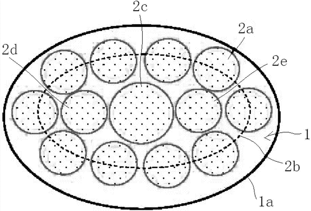
[0064] Such as image 3 As shown, the difference between the elevator tensile rope shown in the figure and the elevator tensile rope of Example 2 is that all the supporting bodies 2a, 2c, 2d, 2e are made of carbon fiber or aramid with high strength and high modulus. Made of fiber-reinforced resin-based composite material. The volume ratio of high-strength and high-modulus carbon fiber or aramid fiber to the resin matrix is ​​not less than 9:1.

[0065] Because the high-strength, high-modulus carbon fiber or aramid fiber resin matrix composite material itself has good bending fatigue resistance, there is no need to reduce the cross-sectional size of the carrier to improve the life. Therefore, the area of ​​the bearing body can be further increased while keeping the overall outer size unchanged, so that the rope has higher bearing capacity and resistance to torsional deformation.


PUM

PropertyMeasurementUnit
Diameteraaaaaaaaaa
Tensile strengthaaaaaaaaaa
Thicknessaaaaaaaaaa

Abstract

The invention discloses a retractable rope used for an elevator. The retractable rope is characterized by being composed of at least one bearing body capable of bearing independently and a wrapping layer, wherein the cross section of the retractable rope is oval, and the short axis of the oval is vertical to the retracting direction of the retractable rope. Compared with a plastic coated wire rope with a circular section, the retractable rope mainly has two advantages that (1) on the condition that the bearing force is the same, the contact area of the retractable rope and a running wheel is increased, the retractable rope is evenly stressed, and service life of a coated layer is prolonged; (2) a plurality of independent bearing bodies in the retractable rope are distributed in parallel, the diameter of each bearing body is 2 mm, according to the requirement in GB7588 that the rope diameter ratio can not be smaller than 40, and the diameter of the running wheel can be reduced to 100m. When the retractable rope is used, a traction pulley needs to have a groove type which is complementary with the appearance of the retractable rope so that the traction pulley can be well meshed with the rope when the elevator operates, the guide performance of the rope is improved and eccentric wear is restrained.

Description

Technical field [0001] The present invention relates to the technical field of elevator ropes, in particular to elevator ropes. Background technique [0002] Traction elevators use two or more steel wire ropes to connect the elevator car and the counterweight. Through the interaction force between the steel wire ropes and the traction sheave, the car is pulled to move up and down to achieve the purpose of transportation of people or goods. The failure and life of the steel wire rope are issues that cannot be ignored in the elevator operation quality and safety. Considering the life of the wire rope and elevator safety, GB7588 requires that the diameter ratio of the traction sheave to the wire rope should not be less than 40:1. The diameter of the traditional steel wire rope is usually ≥8mm, so the corresponding sheave diameter needs to be no less than 320mm. Such a large rope wheel not only reduces the utilization of the hoistway space, but also increases the installation stren...

Claims


Application Information

Patent Timeline
IPC IPC(8): B66B7/06D07B1/02
CPCD07B1/16D07B1/025D07B1/0673D07B5/006D07B2201/1004D07B2201/2018D07B2205/3007D07B2501/2007D07B2801/10
Inventor 刘礼邹志文邓奇
Owner YUNGTAY ELEVATOR EQUIP CHINA
Why Eureka
Try Eureka