
Seven-axis turn-milling machining center

A compound machining center, turning and milling technology, applied in the direction of metal processing equipment, metal processing machinery parts, manufacturing tools, etc., to achieve the effect of prolonging service life, convenient maintenance, and small loss of transmission accuracy

Inactive Publication Date: 2014-04-02
江苏建亚精密机械有限公司
View PDF7 Cites 16 Cited by
  • Summary
  • Abstract
  • Description
  • Claims
  • Application Information

AI Technical Summary

Problems solved by technology

[0004] The machining center is a kind of numerical control machine tool developed from the numerical control milling machine. The machining center is equipped with a tool magazine, which stores different types of tools or inspection tools. During the machining process, the program automatically selects and replaces them. Milling, The functions of boring, drilling, tapping and thread cutting are concentrated on one machine tool; while the turning and milling compound machining center is a CNC machine tool with turning and milling functions at the same time, with more comprehensive functions and more types of workpieces that can be processed , the number of axes of the turn-milling compound machining center is a key factor in its performance. At present, there is no seven-axis turn-milling compound machining center that can process workpieces more flexibly and conveniently.

Method used


Image

  • Seven-axis turn-milling machining center
  • Seven-axis turn-milling machining center
  • Seven-axis turn-milling machining center

Examples


Embodiment Construction

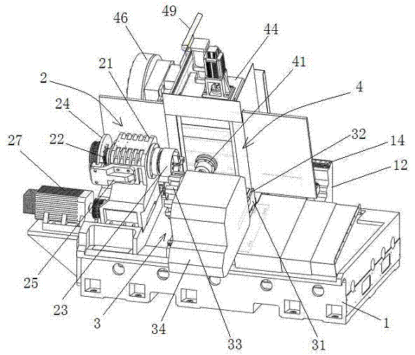
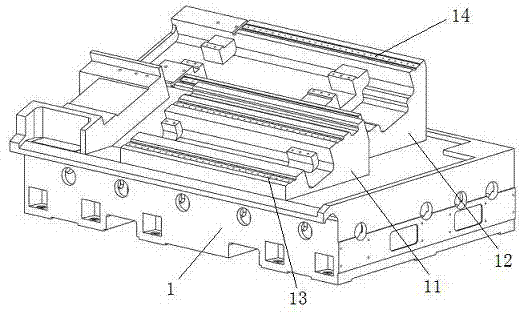
[0028] Such as figure 1 , figure 2 , image 3 , Figure 4 The seven-axis turning-milling compound machining center shown includes a base 1 and a bed set on the base 1, the bed is composed of a slanted bed A11 and a slanted bed B12 arranged side by side, and the slanted bed A11 The upper surface of the inclined bed A11 and the inclined bed B12 are inclined to the same side, and the upper surfaces of the inclined bed A11 and the inclined bed B12 are respectively provided with X-axis A guide rail 13 and X-axis B guide rail 14 parallel to each other; it also includes workpiece clamping Device 2, turning device 3 and milling device 4;

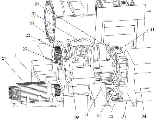
[0029] The workpiece clamping device 2 includes a spindle box 21 connected to the same end of the inclined bed A11 and the inclined bed B12 at both ends of the bottom, and a spindle 22 connected to the spindle box 21. The spindle hole of the spindle box 21 has interference A shaft sleeve 26 is connected, and the main shaft 22 is rotatably conne...


PUM


Abstract

The invention discloses a seven-axis turn-milling machining center. The machining center comprises a base, a lathe body arranged on the base, a work-piece clamping unit, a turning unit and a milling unit. An X-axis guide rail A and an X-axis guide rail B which are parallel are arranged on the lathe body. The work-piece clamping unit comprises a spindle box connected with one end of the lathe body and a spindle connected with the spindle box, a work-piece clamp is arranged at one end of the spindle, which faces towards the lathe body, and the end of the spindle, which face towards the lathe body, performs transmission with the motor. A saddle A of the turning unit and a saddle B of the milling unit are connected with the X-axis guide rail A and the X-axis guide rail B through a transmission unit A and a transmission unit B respectively, and a turning tool of the turning unit and a milling electric spindle of the milling unit face towards the work-piece clamp respectively. According to the seven-axis turn-milling machining center, the arrangement is reasonable, the structure is compact, four-axis linkage can be performed during turning or milling, and work-piece machining is flexible and convenient.

Description

technical field [0001] The invention relates to the field of machining centers, in particular to a seven-axis turning-milling compound machining center. Background technique [0002] Machine tools refer to machines that manufacture machines, also known as machine tools or tool machines, which are customarily referred to as machine tools and are generally divided into metal cutting machine tools, forging machine tools and woodworking machine tools. There are many ways to process mechanical parts in modern machinery manufacturing. In addition to cutting, there are casting, forging, welding, stamping, extrusion, etc., but for parts with high precision requirements and finer surface roughness requirements, they generally need to be processed. The cutting method is used for final processing on the machine tool, and the machine tool plays an important role in the modernization of the national economy. [0003] Common types of machine tools include lathes that use tools to turn ro...

Claims


Application Information

Patent Timeline
IPC IPC(8): B23P23/02
CPCB23P23/02B23Q1/015B23Q1/017B23Q1/70B23Q5/20B23Q11/0825
Inventor 陈钒陈蜀中方敏陈益王
Owner 江苏建亚精密机械有限公司
Learn More