Seawater desalting device

A seawater and water storage tank technology, applied in seawater treatment, general water supply saving, heating water/sewage treatment and other directions, can solve the problems of inconvenient portability, reduced energy utilization rate of the device, large volume, etc., to improve heat utilization efficiency, Good condensation and heat reduction effect

Inactive Publication Date: 2014-04-02
CHINA UNIV OF GEOSCIENCES (WUHAN)
View PDF10 Cites 11 Cited by
  • Summary
  • Abstract
  • Description
  • Claims
  • Application Information

AI Technical Summary

Problems solved by technology

But the heat conduction cover of this device is arranged on the containing part and cannot effectively provide the required energy of the whole device
Chinese patent CN201195697Y discloses a new type of miniature seawater desalination device, including a manual booster pump, an organic filter pump, a hyperbaric chamber and a casing. The device is small in size and easy to carry but needs to be manually pressurized; Manual seawater desalination device, including coarse filter, reverse osmosis pretreatment component, manual high-pressure pump, pressure regulator valve and reverse osmosis membrane component, the device is composed of two separate parts, namely seawater pretreatment part and reverse osmosis treatment part, so This seawater desalination device is bulky and inconvenient to carry
[0005] Compared with Chinese patent CN2687107Y, a gas-liquid mixing high-speed evaporation seawater desalination device is disclosed, which is composed of a transparent vaporization greenhouse, a hurricane cover, a blower, a pressure injection device and a diffuser. The device has low cost and stable performance, but cannot be used in the mixing chamber. Ensure that seawater droplets and air can be fully evaporated and vaporized after being mixed with high pressure and high speed; on the other hand, the energy utilization rate of the device is reduced

Method used


Image

  • Seawater desalting device
  • Seawater desalting device
  • Seawater desalting device

Examples


Embodiment Construction

[0019] The present invention will be described in detail below in conjunction with the accompanying drawings.

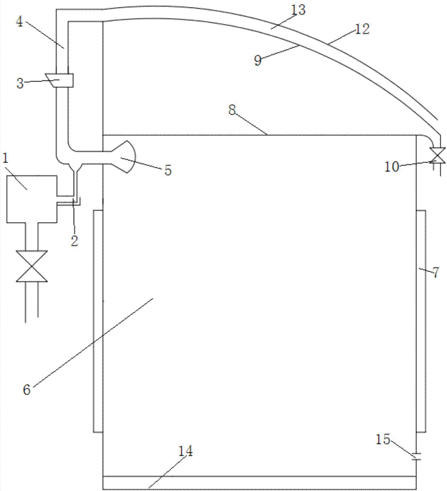
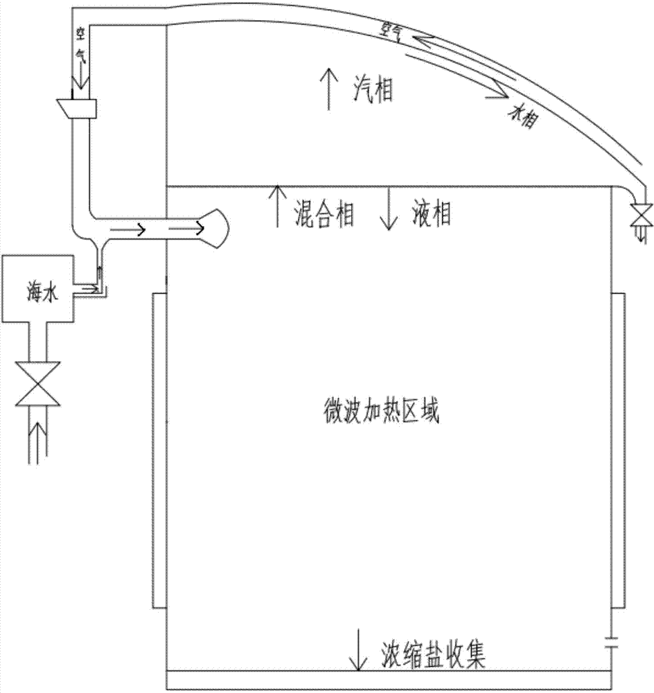
[0020] The overall structure of the seawater desalination device provided by the present invention is as follows: figure 1 As shown, it includes a water storage tank 1, an ultrasonic atomizer 2, a gas-liquid mixing unit, an evaporation condensation unit, and a pipeline connecting the above-mentioned components, wherein the water storage tank 1 stores seawater, and the ultrasonic atomizer 2 The water storage tank 1 is connected through pipelines, and the seawater in the water storage tank is atomized into small liquid droplets. Because the ultrasonic wave has the effect of destroying the inertia of the liquid surface and the surface tension to produce cavitation, when the surface tension wave of the liquid is sufficient, it will The mist will fly out at the peak; the difference in the diameter of the atomized particles leads to the difference in the evaporation rate, ...


PUM


Abstract

The invention provides a seawater desalting device. The seawater desalting device at least comprises a water storage tank, an ultrasonic atomizer, a gas-liquid mixing unit, an evaporating and condensing unit, and pipelines used for enabling the parts to be communicated with each other, wherein seawater is stored in the water storage tank, and the ultrasonic atomizer is connected with the water storage tank through the pipeline; the gas-liquid mixing unit consists of an air compressor, a gas inlet pipeline and a nozzle; the evaporating and condensing unit at least comprises an evaporator, a microwave heater, a grating filter, a condensing deflector and a water outlet pipe, a hollow evaporating cavity is formed inside the evaporator, the microwave heater is mounted on the inner wall of the evaporating cavity, the grating filter covers the top of the evaporating cavity, the condensing deflector is mounted above the grating filter, and a deflecting trench is formed in the condensing deflector. The device has the advantages that sprayed liquid drops are small; uniformity of atomized liquid drops is good; evaporating speed is high; energy utilization rate is high during the evaporation of water by a microwave heating method; the size of atomized particles can be adjusted; the energy utilization rate is high.

Description

technical field [0001] The invention provides a seawater desalination device, in particular to a gas-liquid mixed low energy consumption and high-efficiency seawater desalination device, which belongs to the technical field of seawater desalination devices. Background technique [0002] With the rapid development of economy and society and the increasing destruction of environmental resources, the crisis of water resources has become the second largest environmental problem in the world after global warming. About 70% of the earth is covered by oceans, so seawater desalination is an inevitable choice to solve the water crisis and develop new safe water sources. At present, there are many types of seawater desalination technologies at home and abroad. Although the multi-stage flash technology is mature, it consumes a lot of power; the low-temperature multi-effect distillation technology has a complex structure and high cost; It is continuously decreasing, but there is still ...

Claims


Application Information

Patent Timeline
Patent Type & Authority Applications(China)
IPC IPC(8): C02F1/04C02F1/30C02F1/36C02F103/08
CPCY02A20/124
Inventor 龚蕊张大鹏王朝晖周成冈吴金平
Owner CHINA UNIV OF GEOSCIENCES (WUHAN)
Why Eureka
Try Eureka