Vacuum reaction chamber and vacuum processing equipment

A reaction chamber and vacuum technology, applied in vacuum evaporation plating, metal material coating process, ion implantation plating, etc., can solve the problems of reducing equipment utilization rate, inaccurate spectral detection, waste of manpower, etc., to reduce costs and manpower loss, guaranteed observation effect, and overall life extension effect

Active Publication Date: 2015-09-30
HEFEI BOE OPTOELECTRONICS TECH +1
View PDF5 Cites 0 Cited by
  • Summary
  • Abstract
  • Description
  • Claims
  • Application Information

AI Technical Summary

Problems solved by technology

[0003] The observation windows of existing vacuum processing equipment do not include protective facilities, which results in long-term exposure of the observation windows to the process reaction environment. After a period of time, the observation windows cannot be used normally due to glass atomization, and have to be replaced regularly, wasting a lot Manpower, material resources, and indirectly reduce the utilization rate of equipment; and part of the reaction requires the operator to detect the spectrum of reactants and products through the observation window to control the reaction time. Since the observation window is atomized by plasma, the spectrum detection is inaccurate And further lead to insufficient etching, which seriously affects product quality; on the other hand, the inner wall plate of the vacuum reaction chamber will be etched by the plasma and reactants during the etching process, resulting in the loss of the inner wall plate oxide layer, and the inner wall plate is conductive. It greatly shortens the service life of the inner wall panels, wasting a lot of money, and at the same time the replacement of the wall panels also wastes manpower, reduces the utilization rate of equipment, and affects production efficiency

Method used


Image

  • Vacuum reaction chamber and vacuum processing equipment
  • Vacuum reaction chamber and vacuum processing equipment
  • Vacuum reaction chamber and vacuum processing equipment

Examples


Embodiment 1

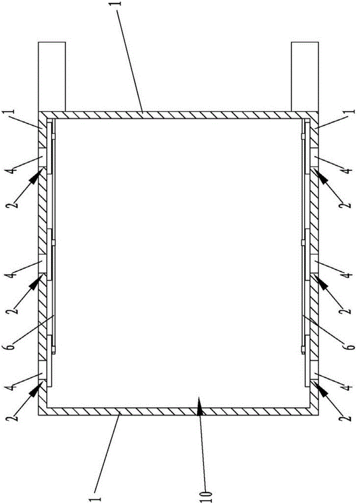
[0030] Such as figure 1 , figure 2 As shown, the embodiment of the vacuum reaction chamber of the present invention includes a plurality of wall plates 1 , and the plurality of wall plates 1 surround and form a chamber 10 for accommodating workpieces. Chamber 10 is rectangular. At least one wall plate 1 in the plurality of wall plates 1 is provided with an observation device 2, and the observation device 2 includes an observation window 4 arranged on the wall plate 1 and an observation window 4 arranged on the side of the wall plate 1 facing the inside of the chamber 10. It is used to block the shielding plate 3 of the observation window 4. The shielding plate 3 is located inside the chamber 10 . The blocking plate 3 can move between a first position 11 for blocking the observation window 4 and a second position 12 for not blocking the observation window 4 .

[0031] figure 2 The structure of the observation device 2 inside the chamber 10 is shown. In the embodiment of...

Embodiment 2

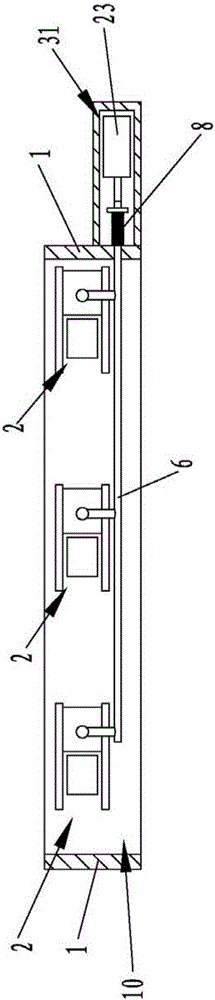
[0055] combine image 3 As shown, the difference between the embodiment of the vacuum reaction chamber of the present invention and the first embodiment is only the difference in power components, wherein the power component 31 of this embodiment is the cylinder 23, the piston rod of the cylinder 23 and the other end of the spring tube 8 Connection, the controller is connected with the cylinder 23, and the controller controls the movement of the shutter plate 3 between the first position 11 and the second position 12 by controlling the movement of the piston rod of the cylinder 23.

Embodiment 3

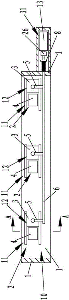
[0057] combine Figure 4 Shown, the embodiment of the vacuum reaction chamber of the present invention, wherein, one end of the spring tube 8 is connected with the end protruding from the inside of the chamber 10 of the movement rod 6, and the other end of the spring tube 8 is connected with a handle 25, and the handle 25 The shielding plate 3 is moved between the first position 11 and the second position 12 by driving the spring tube 8 to extend or compress.

[0058] The vacuum processing equipment of the present invention includes the vacuum reaction chamber of the present invention.

[0059] The vacuum reaction chamber of the present invention uses ceramic materials with high temperature resistance, corrosion resistance and ion bombardment resistance to make the shielding plate. When using the observation window for observation, the shielding plate can be opened manually or automatically; when the observation window is not used in normal production, the shielding plate can ...


PUM


Abstract

The invention discloses vacuum reaction chamber and vacuum processing equipment. The vacuum chamber comprises a plurality of wallboards, wherein an observation device is arranged on at least one wall boards of the plurality of wallboards; the observation device comprises an observation window arranged on the wallboard and a shielding plate for shielding the observation window; the shielding plate can be moved between a first position for shielding the observation window and a second position not shielding the observation window. The vacuum processing equipment comprises the vacuum reaction chamber. In the vacuum reaction chamber and the vacuum processing equipment, the shielding plate can protect the observation window and further effectively shield the wallboard around the observation window. The vacuum reaction chamber and the vacuum processing equipment can effectively protect the observation window, prolongs the service life of the observation window, and effectively ensures the observation effect; meantime, the shielding plate can protect the wallboard around the observation window, namely the etched place with highest etching possibility on the wallboard, so as to prolong the entire service life of the wallboard and reduce the cost for high-frequency maintenance and labor loss.

Description

technical field [0001] The invention relates to vacuum etching and vacuum coating equipment in the photovoltaic industry, semiconductor industry, and liquid crystal panel industry, in particular to a vacuum reaction chamber and vacuum processing equipment. Background technique [0002] Vacuum reaction chambers in vacuum etching equipment or vacuum coating equipment often used in the photovoltaic industry, semiconductor, and liquid crystal panel industries are generally made of opaque metal materials. This kind of vacuum reaction chamber is generally equipped with an observation window made of transparent quartz glass, so that the operator can observe the internal conditions of the vacuum equipment when the production is abnormal or when monitoring for some purpose. [0003] The observation windows of existing vacuum processing equipment do not include protection facilities, which results in long-term exposure of the observation windows to the process reaction environment. Af...

Claims


Application Information

Patent Timeline
Patent Type & Authority Patents(China)
IPC IPC(8): C23C14/52C23C14/00C25F3/02C25F7/00
Inventor 王轶南张福刚张巍刘祖宏侯智吴代吾
Owner HEFEI BOE OPTOELECTRONICS TECH
Why Eureka
Try Eureka