Gasification system for carbon-containing fuel

A gasification system and fuel gasification technology, applied in the manufacture of combustible gas, chemical industry, joint combustion mitigation, etc., can solve the problems of inability to efficiently use high-temperature water to discharge heat, and achieve the effect of carbon loss and waste reduction

Active Publication Date: 2014-04-09
MITSUBISHI POWER LTD +1
View PDF11 Cites 2 Cited by
  • Summary
  • Abstract
  • Description
  • Claims
  • Application Information

AI Technical Summary

Problems solved by technology

In this case, at the outlet of the heat exchanger, the high-temperature water drawn from the slag cooling water storage part is higher than the normal temperature, and the exhaust heat of the high-temperature water cannot be efficiently used.

Method used


Image

  • Gasification system for carbon-containing fuel
  • Gasification system for carbon-containing fuel
  • Gasification system for carbon-containing fuel

Examples


Embodiment 1)

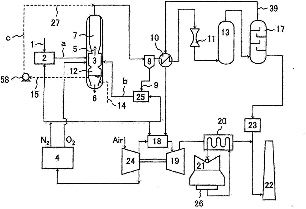
[0030] quote figure 1 , the combined coal gasification power generation facility equipped with the carbon-based fuel gasification system according to the first embodiment of the present invention will be described.

[0031] figure 1 The carbon-based fuel gasification system of the present example shown efficiently utilizes the sensible heat of high-temperature water generated in the cooling water storage part of the molten slag to cool the product gas obtained by gasifying the carbon-based fuel. Carbon-based fuel gasification system with miniaturized heat recovery unit.

[0032] Taking the case where coal is used as fuel and gas turbines and steam turbines are driven by generated gas as an example, use figure 1 A carbon-based fuel gasification system according to a first embodiment of the present invention will be described.

[0033] figure 1It is a system diagram showing the structure of a combined coal gasification power generation facility equipped with a carbon-based f...

Embodiment 2)

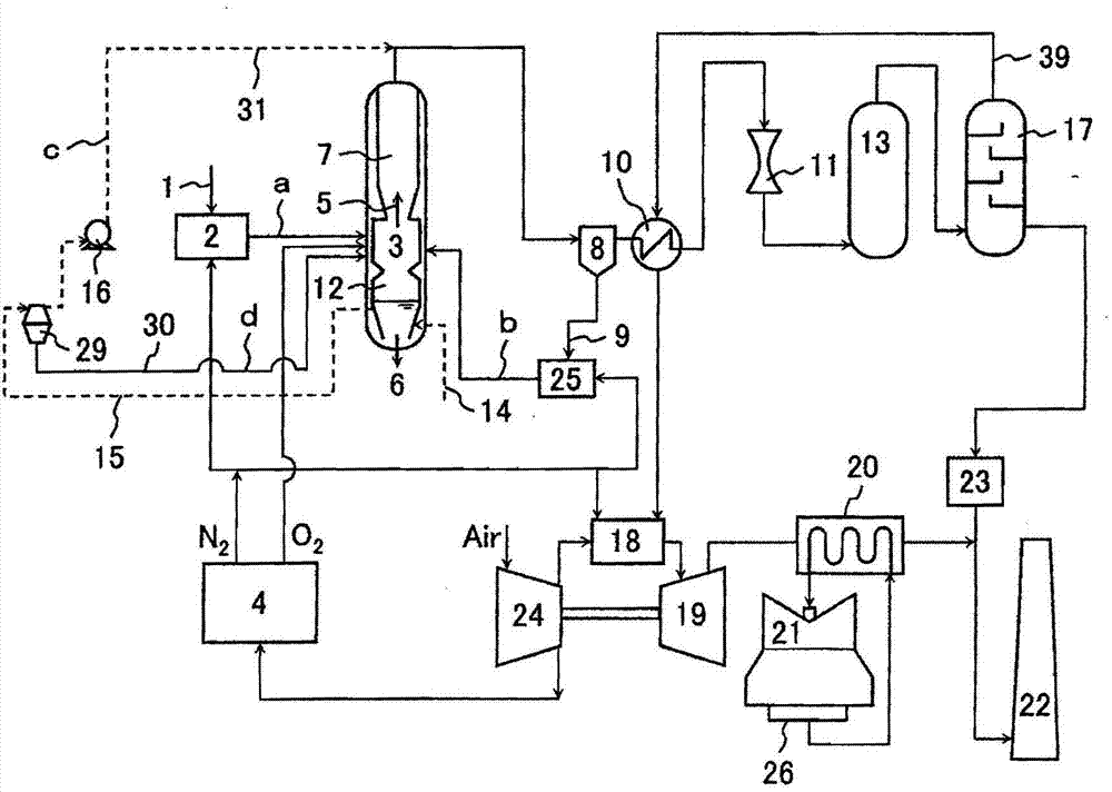
[0072] Next, use figure 2 A combined coal gasification power generation facility equipped with a carbon-based fuel gasification system according to a second embodiment of the present invention will be described. figure 2 The shown coal gasification combined power generation equipment equipped with the gasification system of the carbon-based fuel of this embodiment figure 1 The shown coal gasification combined power plant equipped with the carbon-based fuel gasification system of the first embodiment has the same basic structure, so the description of the common structure will be omitted, and the different structure will be described below.

[0073] exist figure 2 In the carbon-based fuel gasification system of the present embodiment shown, for the high-temperature water 15 heated by molten slag in the slag cooling water reservoir 12 directly below the gasification furnace 3, the slag cooling water The storage part 12 is extracted by the water supply system c and supplied ...

Embodiment 3)

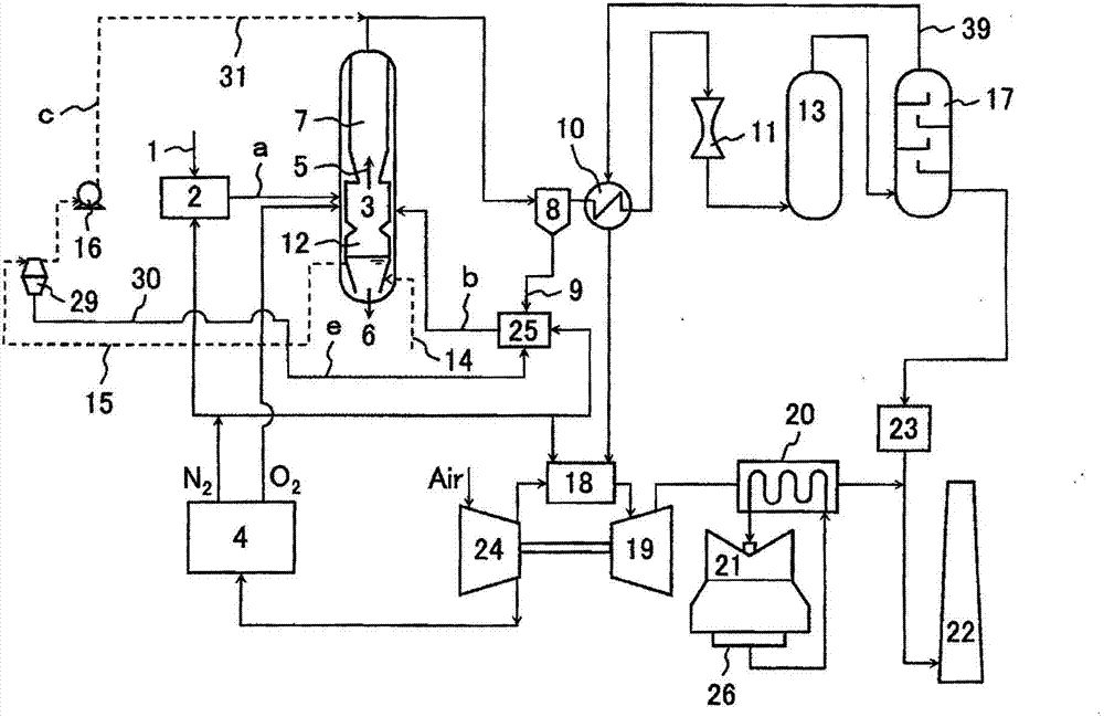
[0083] Next, use image 3 A combined coal gasification power generation facility equipped with a carbon-based fuel gasification system according to a third embodiment of the present invention will be described. image 3 The shown coal gasification combined power generation equipment equipped with the gasification system of the carbon-based fuel of this embodiment figure 1 The shown coal gasification combined power plant equipped with the carbon-based fuel gasification system of the first embodiment has the same basic structure, so the description of the common structure will be omitted, and the different structure will be described below.

[0084] exist image 3 In the carbon-based fuel gasification system of the present embodiment shown, for the high-temperature water 15 heated by molten slag in the slag cooling water reservoir 12 directly below the gasification furnace 3, the slag cooling water The storage part 12 is extracted by the water supply system c and supplied to t...


PUM


Abstract

The present invention provides a gasification system for carbon-containing fuel that achieves both the utilization of high-temperature waste water and waste heat generated by a gasifier and the reduction in the equipment and construction costs of the gasifier. In a gasifier (3) for gasifying carbon-containing fuel, high-temperature water is pulled out from a slag-cooling water pool (12) at the bottom of the gasifier, and fed to the downstream side of the gasifier or the upstream side of a dust removing part (8) through a water supply system (c) so as to be mixed with a syngas, thereby cooling the syngas. Thus, a heat recovery part (7) of the syngas can be miniaturized or eliminated. The high-temperature water pulled out from the slag-cooling water pool is easily evaporated while being mixed with the syngas, such that the syngas can be cooled with high efficiency. Solids in the high-temperature water pulled out from the slag-cooling water pool are recovered by the duct removing part with the syngas, and fed into the gasifier again. Thus, the utilization of the waste heat of the high-temperature water is realized, and the carbon loss and waste material are reduced.

Description

technical field [0001] The present invention relates to a gasification system for carbon-based fuels such as coal, in particular to a gasification system for carbon-based fuels that takes into account both drainage and waste heat utilization and waste reduction. Background technique [0002] The product gas produced by gasifying carbon-based fuel such as coal reaches 1000°C or higher at the outlet of the gasifier. In order to purify the generated gas by removing dust, impurities such as chlorine components and sulfur components, it is necessary to cool the generated gas to less than 400°C. In gasification systems for power generation, energy efficiency is improved by recovering heat when the produced gas is cooled. [0003] The generated gas from the gasification furnace is accompanied by a large amount of solid matter consisting of unburned carbon and ash components. Therefore, in the process of cooling while recovering heat from the generated gas, it is necessary to prev...

Claims


Application Information

Patent Timeline
Patent Type & Authority Applications(China)
IPC IPC(8): C10J3/00C10J3/72C10J3/84
CPCY02E20/18Y02P20/10Y02P20/129
Inventor 石贺琢也木曾文彦流森文彦山藤正德池田健一
Owner MITSUBISHI POWER LTD
Why Eureka
Try Eureka