
Hybrid power device and system and power output construction method adopting fuel and liquid gas

A hybrid power system and hybrid power technology, applied in the direction of pump devices, combustion engines, liquid variable displacement machinery, etc., can solve the problems of dust particles polluting the environment, the reuse rate is only 9%, and the consumption is large. loss, icing avoidance, and fuel usage reduction

Active Publication Date: 2014-04-09
苏州正美光电科技有限公司
View PDF6 Cites 5 Cited by
  • Summary
  • Abstract
  • Description
  • Claims
  • Application Information

AI Technical Summary

Problems solved by technology

However, in the process of realizing this technology, high-pressure storage needs to consume 30% of the energy, and 30% of the energy is lost in the release and filling process, that is, the reuse rate of this method is only about 9%.
On this basis, the energy utilization rate of the internal combustion engine using this treatment method can only reach 20%-30%
[0005] In addition, the existing internal combustion engine consumes a lot of energy substances such as fossil fuels, and the emission of soot particles after fuel combustion directly pollutes the environment. Therefore, it is restricted by the relevant requirements for energy conservation and emission reduction.

Method used


Image

  • Hybrid power device and system and power output construction method adopting fuel and liquid gas
  • Hybrid power device and system and power output construction method adopting fuel and liquid gas
  • Hybrid power device and system and power output construction method adopting fuel and liquid gas

Examples


Embodiment 1

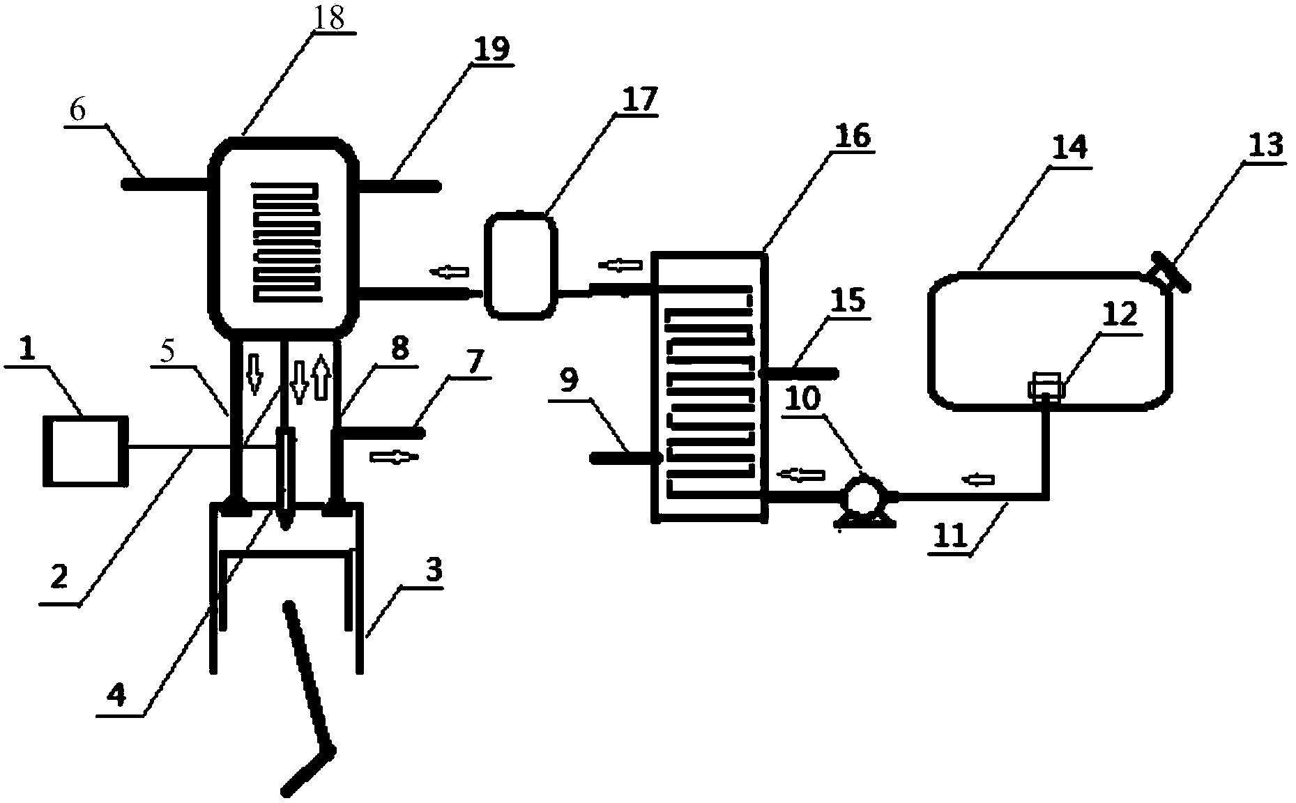
[0053] See figure 2 , which shows the principle diagram of the hybrid power system using liquid gas according to the first embodiment.

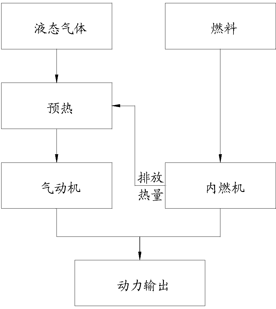
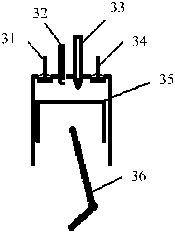
[0054] It should be noted that the power device used in the hybrid power system uses liquid gas and traditional fuel as the basic source of work, and is specifically composed of two main parts: an internal combustion engine cylinder and an air motor cylinder; among them, those skilled in the art can use existing Technology realizes the four-stroke internal combustion engine cylinder part, so in order to show the core design of the application more clearly, only the pneumatic part of the hybrid power system is shown in detail in the figure.

[0055] like figure 2 As shown, the adiabatic liquid storage tank 14 of the hybrid power system is used to store liquid nitrogen to fill and provide nitrogen as the "fuel" of the pneumatic motor. Specifically, the filling can be realized through the liquid filling port 13 opened on the adiabatic liquid ...

Embodiment 2

[0071] This embodiment is basically the same as the hybrid power system using fuel and liquid gas described in the first embodiment, and is further optimized on the basis of the first embodiment. See Figure 5 , which shows the schematic diagram of the hybrid power system using fuel and liquid gas according to the second embodiment. In order to clearly show the difference between the two, the same functional elements are marked with the same symbols in the figure.

[0072] Compared with the first embodiment, this solution has been improved in two aspects. First, the heat exchange preheater 18 also has a second heat source branch, which communicates in parallel with the internal combustion engine exhaust pipeline of the power plant, that is, its internal combustion engine exhaust inlet 20 and internal combustion engine exhaust outlet 21 communicate with the internal combustion engine. Exhaust pipeline, thereby further utilizing the exhaust heat of the internal combustion engi...


PUM


Abstract

The invention discloses a hybrid power device adopting fuel and liquid gas. The hybrid power device comprises a four-stroke internal combustion engine cylinder and a pneumatic motor cylinder, wherein the pneumatic motor cylinder consists of a cylinder body, a piston and a cylinder cover, the piston is arranged in the cylinder body, the cylinder cover, the cylinder body and the piston are enclosed to define a gas source working cavity, and a gas inlet door, a gas outlet door and a spray nozzle extending into the gas source working cavity are arranged on the cylinder cover; the piston of the pneumatic motor cylinder and a piston of the internal combustion engine cylinder are connected with each other through a connecting rod mechanism, and slide alternatively in the corresponding cylinder bodies. The liquid gas and the fuel are adopted as basic sources for forming driving force, the gas emitted after the liquid gas does work can be effectively utilized as a pre-compressed gas source for further heat expansion, so that the efficiency can be furthest improved, and the pollution can be reduced. On the basis, the invention further provides a hybrid power system applying the power device and a hybrid power output construction method adopting fuel and liquid gas.

Description

technical field [0001] The invention relates to the technical field of engines, in particular to a hybrid power device, system and power output construction method using fuel and liquid gas. Background technique [0002] With the rapid development of human society, a large number of power machines have been widely used and have become an indispensable part of human society. As we all know, the existing ways of using power mechanical energy have brought serious damage to the natural environment, for example, the generation of environmental pollution such as heat energy emissions, greenhouse gas emissions, and soot particulate matter emissions, resulting in global warming, sea level rise, and climate change. Bad and other issues. [0003] Among them, the internal combustion engine with relatively mature technology is widely used in automobiles and various operating equipment, and the power output is realized by converting the chemical energy of the fuel into mechanical energy...

Claims


Application Information

Patent Timeline
Patent Type & Authority Applications(China)
IPC IPC(8): F04B41/02F02G5/04
CPCY02T10/166Y02T10/12
Inventor 苟仲武
Owner 苏州正美光电科技有限公司
Learn More