Continuous laser device spectral line width measurement device based on optical frequency comb

An optical frequency comb and laser technology, applied in spectrum investigation and other directions, can solve problems such as the detection of short-term stability and long-term stability of continuous laser linewidth, the reduction of fiber laser output power, and enhanced stimulated Brillouin scattering. , achieve the effect of suppressing the stimulated Brillouin scattering effect, simple structure, and avoiding complex adjustment

Active Publication Date: 2014-04-09
SHANGHAI LANGYAN OPTOELECTRONICS TECH +1
View PDF10 Cites 37 Cited by
  • Summary
  • Abstract
  • Description
  • Claims
  • Application Information

AI Technical Summary

Problems solved by technology

This not only brings inconvenience to the actual operation, but also enhances the stimulated Brillouin scattering (SBS, stimulated Brillouin scattering) effect during the laser transmission process, resulting in adverse effects such as reduced output power of the fiber laser and deterioration of beam quality; at the same time, the current There are methods that cannot realize the detection of short-term stability and long-term stability of continuous laser linewidth

Method used


Image

  • Continuous laser device spectral line width measurement device based on optical frequency comb
  • Continuous laser device spectral line width measurement device based on optical frequency comb
  • Continuous laser device spectral line width measurement device based on optical frequency comb

Examples


Embodiment 1

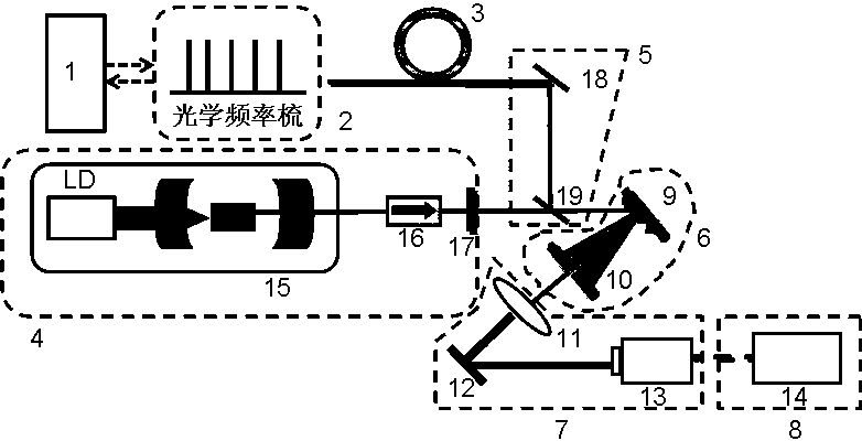
[0041] refer to figure 2 , is a schematic diagram of using a 1064nm solid-state laser as the laser to be tested to measure its output spectral width with an optical frequency comb. In the figure: 1-optical frequency comb control module; 2-optical frequency comb seed source; 3-optical frequency comb spectrum broadening module That is, photonic crystal fiber; 4-continuous laser source (composed of 1064nm continuous laser module 15, 1064nm polarization isolator 16, 1064nm space half-wave plate 17); 6-optical frequency-selective filtering module (consisting of 1 μm band reflective grating 9 and aperture diaphragm 10); 7-beat frequency detection module (consisting of converging lens 11, 1064nm high reflection mirror 12, Avalanche photodetector 13); 8-signal reading module (composed of fast Fourier transform analyzer 14).

[0042] Implementation details:

[0043] (1) The optical frequency comb seed source 2 outputs a highly stable mode-locked pulse sequence in the time domain and...

Embodiment 2

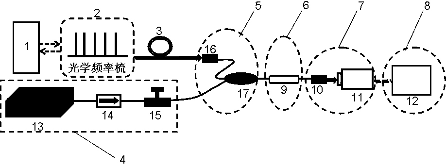
[0052] refer to image 3 , is a schematic diagram of using a 1550nm fiber laser as the laser to be tested to measure its output spectrum width with an optical frequency comb. In the figure: 1-optical frequency comb control module; 2-optical frequency comb seed source; 3-optical comb spectrum broadening module That is, photonic crystal fiber; 4-continuous laser source (composed of 1550nm continuous laser module 13, 1550nm fiber isolator 14 and fiber polarization controller 15); 5-optical beam combination module (composed of fiber collimator 16, 1550nm band optical fiber coupler 17); 6-optical frequency selection filter module (composed of 1550nm band fiber narrowband filter 9); 7-beat frequency detection module (composed of fiber collimator 10, avalanche photodetector 11); 8-signal A reading module (consisting of an electrical filter and a data acquisition card 12).

[0053] Implementation details:

[0054] (1) The optical frequency comb seed source 2 outputs a highly stable ...

Embodiment 3

[0065] refer to Figure 4 , is a schematic diagram of simultaneously measuring the output linewidth of two CW lasers at 657nm and 423nm with an optical frequency comb. In the laser frequency standard module based on calcium atoms, it is necessary to excite calcium ions with a beam of 423nm laser first to make it achieve the laser transition at the energy level of 657nm, so real-time measurement and control of the linewidth of 423nm and 657nm laser is very important. In the figure: 1-optical frequency comb control module; 2-optical frequency comb seed source; 3-optical comb spectrum broadening module is photonic crystal fiber; 4-continuous laser generation source (consisting of 423nm continuous laser module 20, visible light band polarization isolator 22. Visible light band half-space wave plate 24 and lens group 10); 4 , - Continuous laser source (composed of 657nm continuous laser module 21, visible light band polarization isolator 23, visible light band space half-wave plat...


PUM


Abstract

The invention discloses a continuous laser device spectral line width measurement device based on an optical frequency comb. The continuous laser device spectral line width measurement device is characterized by comprising an optical frequency comb control module, an optical frequency comb seed source, an optical frequency comb spectrum broadening module, a continuous laser generating source, an optical beam combining module, an optical frequency selecting filtering module, a beat frequency detecting module and a signal reading module. The spectrum of the precisely-controlled optical frequency comb is broadened, output light of the precisely-controlled optical frequency comb and output light of the continuous laser generating source together enter the optical beam combining module, the light spots of two outgoing laser beams coincide, and then the two laser beams together enter the optical frequency selecting filtering module, two laser beams obtained through filtering pass through the beat frequency detecting module, the sizes of light spots are changed through shaping, and the light spots are concentrated on a detector, beat frequency signals are obtained through coherent combination, and the output spectral width of the continuous lasers to be measured can be contained through the signal reading module. The continuous laser device spectral line width measurement device is stable in structure and high in practicability, the measurement process is rapid and simple, and the output spectral width of one or more wave length continuous lasers can be obtained in real time.

Description

technical field [0001] The invention relates to the field of ultrafast lasers, specifically, a precisely controlled mode-locked laser is used to generate a stable optical frequency comb with a narrow pulse linewidth, and then the optical frequency comb is used to beat the output light of the narrow linewidth continuous laser to achieve A fast and effective measuring device for real-time measurement of the output spectral linewidth of continuous lasers with linewidths in the KHz to MHz order. Background technique [0002] Continuous laser and pulsed laser, as two branches in the field of laser technology, have been closely concerned by practitioners in various fields of scientific research, production and life. On the one hand, the ultra-narrow linewidth continuous laser based on the atomic transition line can provide frequency standard reference for many ultrafast laser technologies. At the same time, the emerging narrow linewidth continuous fiber laser has good noise suppre...

Claims


Application Information

Patent Timeline
Patent Type & Authority Applications(China)
IPC IPC(8): G01J3/28
Inventor 白东碧曾和平
Owner SHANGHAI LANGYAN OPTOELECTRONICS TECH
Why Eureka
Try Eureka