Ethernet traffic generation and analysis method based on Ethernet switch chip

A switching chip and Ethernet technology, which is applied in the field of Ethernet traffic generation and analysis, can solve problems such as test environment impact, high R&D cost, and technical difficulty, and achieve large device volume and port density, reduce R&D costs, and low noise Effect

Inactive Publication Date: 2014-04-09
潘晶
View PDF5 Cites 31 Cited by
  • Summary
  • Abstract
  • Description
  • Claims
  • Application Information

AI Technical Summary

Problems solved by technology
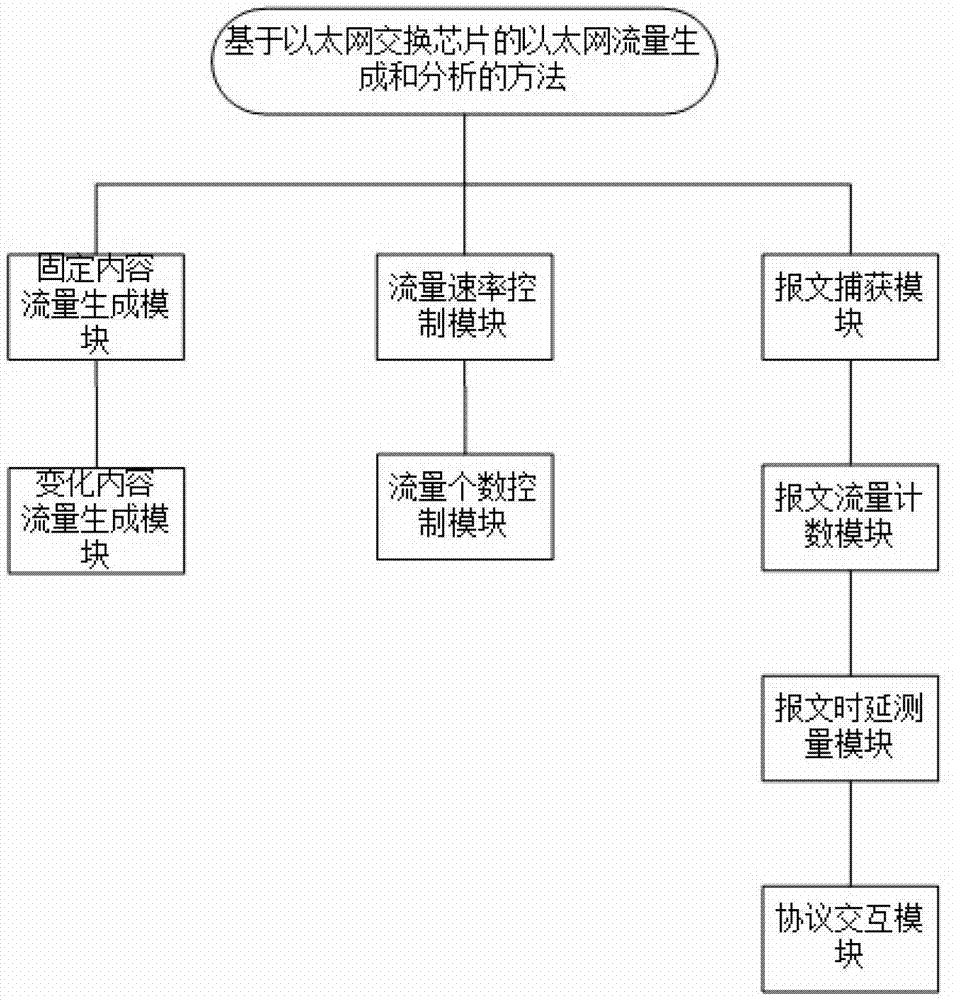
[0003] Existing test equipment generally uses FPGA chips to realize traffic generation and analysis. The research and development costs are high, the cycle is long, and the technology is difficult. At the same time, FPGA has the characteristics of high power consumption. In actual equipment, high-power fans need to be used to assist heat dissipation. The noise generated also has an impact on the test environment

Method used


Image

  • Ethernet traffic generation and analysis method based on Ethernet switch chip
  • Ethernet traffic generation and analysis method based on Ethernet switch chip
  • Ethernet traffic generation and analysis method based on Ethernet switch chip

Examples


Embodiment 1

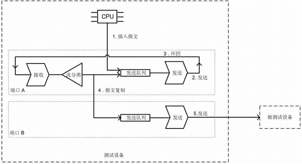
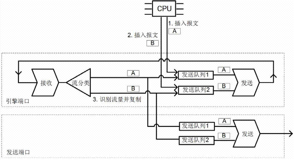
[0101] Embodiment one, such as Figure 15As shown, the device under test is a Layer 2 Ethernet switch, and its forwarding method is based on the search of the destination MAC address. When the search fails, the message is broadcast to all ports (except the receiving port), and when the search is successful, the message is only unicast to the corresponding exit. For the source MAC address of each packet received, the switch will record the information of its receiving port. The test equipment provides three externally visible ports A, B, and C, which are the sending port and the receiving port mentioned above, where A and B respectively have an internal engine port X, Y to provide traffic generation functions for them; The test equipment also provides three externally visible ports as D, E, and F, which have the function of Layer 2 forwarding; ABCDEF all work at a rate of 100 mbps (megabits per second).

[0102] Through the following steps, we will verify the forwarding behav...

Embodiment 2

[0119] Embodiment two, such as Figure 16 As shown, the tested device is a three-layer router, which provides four ports: E, F, G, H, and the rate is 1G bps. Set the routing rule configuration as:

[0120] F port is the interface leading to the 192.168.1.1~192.168.1.254 network segment,

[0121] G port is the interface leading to the 192.168.2.1~192.168.2.254 network segment,

[0122] Port H is the interface leading to the 192.168.3.1~192.168.3.254 network segment,

[0123] The test equipment provides four external ports: A, B, C, and D, all of which have a rate of 1G bps, and an internal engine port X and a delay measurement port Y, all of which have a rate of 1G bps.

[0124] Through the following test flow, we will verify whether the router has routing function and forwarding performance.

[0125] Send three test traffic from port A, which are:

[0126] 1) The destination IP is 192.168.1.100, the frame length is 1500 bytes, the rate is 1000 pps, and the flow is continu...

Embodiment 3

[0138] Embodiment three, such as Figure 17 As shown, the device under test is an Ethernet layer-3 switch, which provides an external port B, which is bound to a layer-3 interface 192.168.1.1, so it will respond to the ARP request message (the query IP is 192.168.1.1), and the test device External port A is provided.

[0139] Through the following steps, we will verify the ARP protocol interaction function of the three-layer switch.

[0140] Step 1: Use the "protocol interaction module" to generate an ARP request message. The specific operation is: the software module on the CPU generates an ARP request message whose IP address is 192.168.1.1, and inserts it into the sending queue of port A, and then reports The file is sent to port B of the device under test;

[0141] Step 2: After the software module on the device under test processes the ARP request message, it generates an ARP reply message and sends it out from port B;

[0142] Step 3: Use the "protocol interaction mod...


PUM


Abstract

According to the invention, the general function of an Ethernet switch chip is used; and based on the general hardware architecture of an Ethernet switch, an Ethernet traffic generation and analysis method is provided, so as to realize two functions of traffic generation and traffic analysis. The method specifically comprises the steps of traffic transmission message content construction, transmission message quantity control, traffic transmission rate control, flow transmission and receiving counting, traffic receiving capturing, forwarding delay measurement and protocol message interaction.

Description

technical field [0001] The invention relates to flow analysis technology in data communication, in particular to a method for generating and analyzing Ethernet flow based on an Ethernet switch chip. Background technique [0002] With the continuous development of the application of Ethernet technology in the field of communication, it can be as small as a home LAN (two-layer switch), as large as an enterprise network and a metropolitan area network (two or three-layer switch, router), or even a backbone network (transmission equipment, backbone router) Ethernet interfaces are widely used, so Ethernet traffic generation and analysis equipment (referred to as test equipment) is produced. For communication equipment with Ethernet interfaces (referred to as tested equipment), test and analysis are carried out in the process of R & D and production. The general test scenario is: one or more physical ports are connected between the test device and the device under test through a n...

Claims


Application Information

Patent Timeline
Patent Type & Authority Applications(China)
IPC IPC(8): H04L12/801
Inventor 潘晶
Owner 潘晶
Why Eureka
Try Eureka