Application of a near-infrared bioluminescence dye in live cell imaging

A fluorescent dye and near-infrared technology, which is applied in the application field of near-infrared bioluminescent dyes in live cell imaging, can solve the problems of incomplete dyeing and large interference

Active Publication Date: 2015-09-16
TECHNICAL INST OF PHYSICS & CHEMISTRY - CHINESE ACAD OF SCI
View PDF2 Cites 0 Cited by
  • Summary
  • Abstract
  • Description
  • Claims
  • Application Information

AI Technical Summary

Problems solved by technology

[0006] The technical problem to be solved by the present invention is that when the existing fluorescent dyes are dyed, they are greatly disturbed by background fluorescence, and the dyeing is not complete, etc.

Method used


Image

  • Application of a near-infrared bioluminescence dye in live cell imaging
  • Application of a near-infrared bioluminescence dye in live cell imaging
  • Application of a near-infrared bioluminescence dye in live cell imaging

Examples


example 1

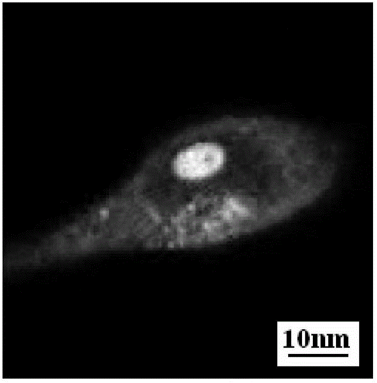
[0122] Hela cells were stained with a near-infrared bioluminescent dye, the fluorescent dye structure is:

[0123]

[0124] figure 1 As shown in , the staining location can be seen: the nucleus is the RNA in the nucleolus.

example 2

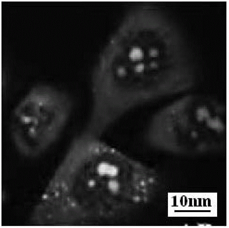
[0126] The near-infrared bioluminescent dye Hela cells used, the structure of the fluorescent dye is:

[0127]

[0128] figure 2 As shown in , the staining location can be seen: the nucleus is the RNA in the nucleolus.

example 3

[0130] Hela cells were stained with a near-infrared bioluminescent dye, the fluorescent dye structure is:

[0131]

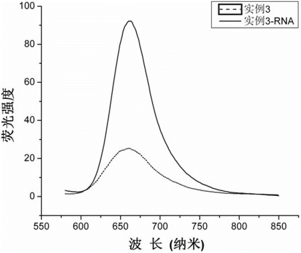
[0132] image 3 It is the fluorescence diagram of the interaction between the compound of Example 3 and RNA; it can be seen that the fluorescence of Example 3 increases with the addition of RNA (200 μg / mL).

[0133] Figure 4 It is the circular dichroism chromatogram of the interaction between the compound of Example 3 and RNA; the change of the circular dichroism spectrum with the increase of the concentration of the compound in the RNA solution, thus it can be deduced that the interaction mode between the RNA and the structure of Example 3 is semi-embedded.

[0134] Figure 5 Add DNase and RNase digestion for Example 3 and compare it with commercially available DNA and RNA dyes, which proves that the compound in Example 3 enters the nucleus and is dyed as RNA. (control is used as a control, that is, blank, CR is the dye of the present invention, Example ...


PUM


Abstract

The invention discloses an application of near infrared bioluminescence dye to living cell imaging; living cell imaging using near infrared bioluminescence dye is completed by the steps of cell culture, dye solution preparation, dyeing and imaging; the invention employs near infrared bioluminescence dye, thereby minimizing damages of cells and tissues caused by light source, and reducing interference of autofluorescence with more thorough dyeing; the near infrared fluorescence dye has specificity for mitochondrial or RNA.

Description

technical field [0001] The invention relates to living cells and imaging, and provides an application of a near-infrared biological fluorescent dye in living cell imaging. Background technique [0002] With the rapid development of life science research, bioluminescent dyes have become more and more widely used in cell immunology, molecular biology, molecular genetics, etc., and have become one of the important tools in life science research. [0003] RNA is ubiquitous in animals, plants, microorganisms, and some viruses and bacteriophages, and RNA and protein biosynthesis are closely related. In RNA viruses and bacteriophages, RNA is the carrier of genetic information. Commonly used RNA imaging methods include; RNA microinjection with fluorescent labels, RNA in situ fluorescence hybridization, RNA staining by green fluorescent protein (GFP) or its derivative YFP labeling proteins that bind to RNA or small molecules of organic dyes imaging. Currently, the only commerciall...

Claims


Application Information

Patent Timeline
Patent Type & Authority Patents(China)
IPC IPC(8): C12Q1/68G01N21/64
CPCG01N33/5079G01N33/582
Inventor 汪鹏飞周炳江刘卫敏陈建宏庄晓青
Owner TECHNICAL INST OF PHYSICS & CHEMISTRY - CHINESE ACAD OF SCI
Why Eureka
Try Eureka