
Position-sensitive readout modes for digital silicon photomultiplier arrays

A detector array and array technology, applied in the field of radiation detection technology, can solve the problems of unrealistic, cumbersome separation equipment, increase system complexity and cost, and achieve the effect of high temporal resolution, high spatial resolution and

Active Publication Date: 2014-04-16
KONINKLJIJKE PHILIPS NV
View PDF6 Cites 19 Cited by
  • Summary
  • Abstract
  • Description
  • Claims
  • Application Information

AI Technical Summary

Problems solved by technology

Disadvantages of PMT detectors include: they are relatively bulky separate devices with large optical windows, these devices operate at high voltages and are prone to failure due to the tube design and high operating voltage
However, this increases system complexity and cost since each SPAD will have its own readout channel
Achieving both high spatial and temporal resolution with SPAD arrays is more difficult
It is usually not practical to provide both individual readouts and individual timestamps for each SPAD detector

Method used


Image

  • Position-sensitive readout modes for digital silicon photomultiplier arrays
  • Position-sensitive readout modes for digital silicon photomultiplier arrays
  • Position-sensitive readout modes for digital silicon photomultiplier arrays

Examples


Embodiment Construction

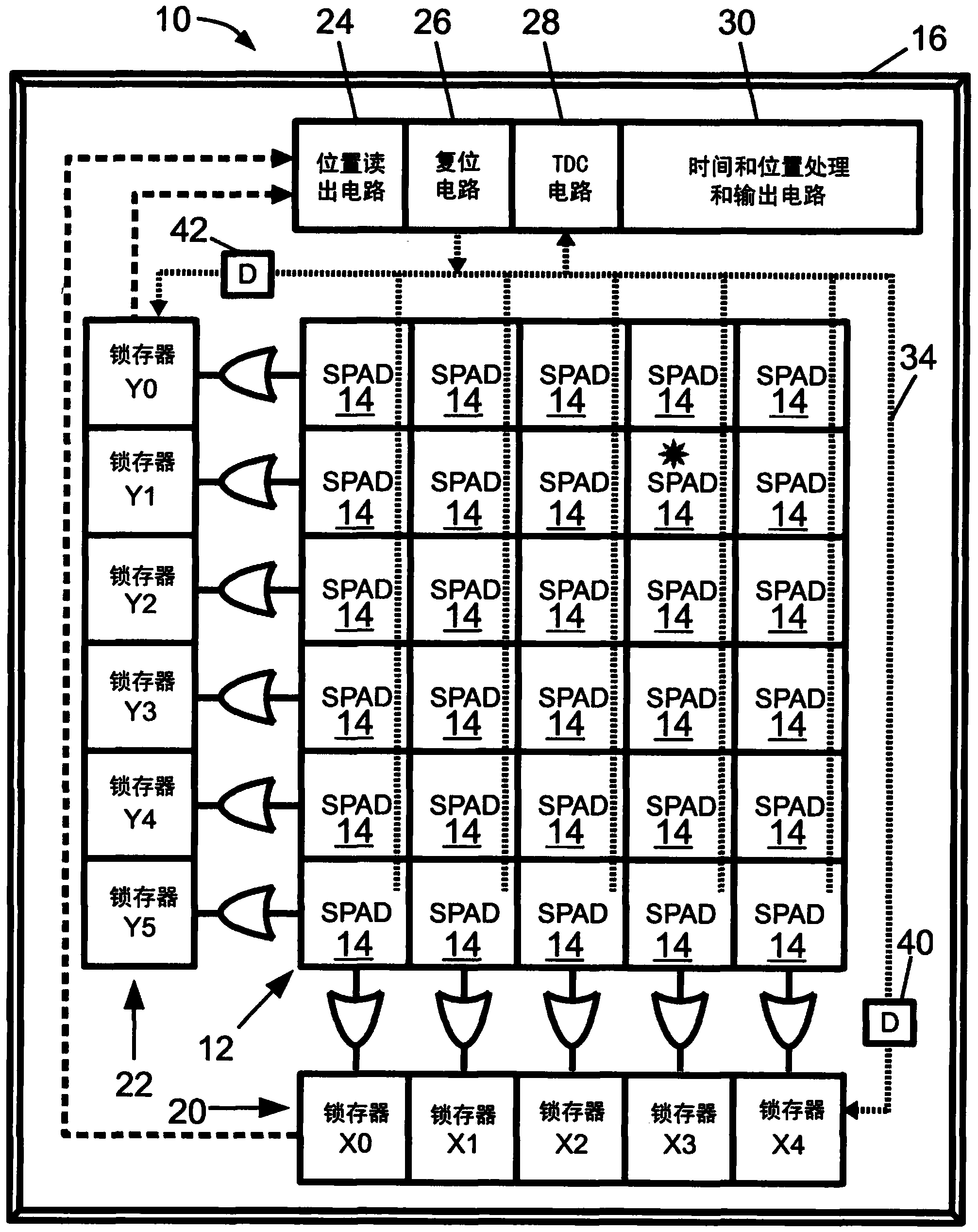
[0021] refer to figure 1 , the photon detector 10 includes a detector array 12 including an array of single photon avalanche diode (SPAD) detectors 14 . Each SPAD detector 14 suitably includes an avalanche diode reverse biased above its breakdown voltage and connected to a quenching circuit, such as a passive voltage drop placed in electrical series with the avalanche diode in some embodiments. resistors, or an active transistor based quenching circuit (details not shown). SPAD detectors operate in photon counting or Geiger mode, where the impact of a single photon on an avalanche diode results in breakdown with subsequent electron multiplication and a large current, which is then quenched by a quenching circuit. The illustrative detector array 12 includes a rectangular array having five columns identified as X0-X4 and six rows identified as Y0-Y5. This is merely illustrative, the detector array can have essentially any number of rows and columns.

[0022] The illustrative ...


PUM


Abstract

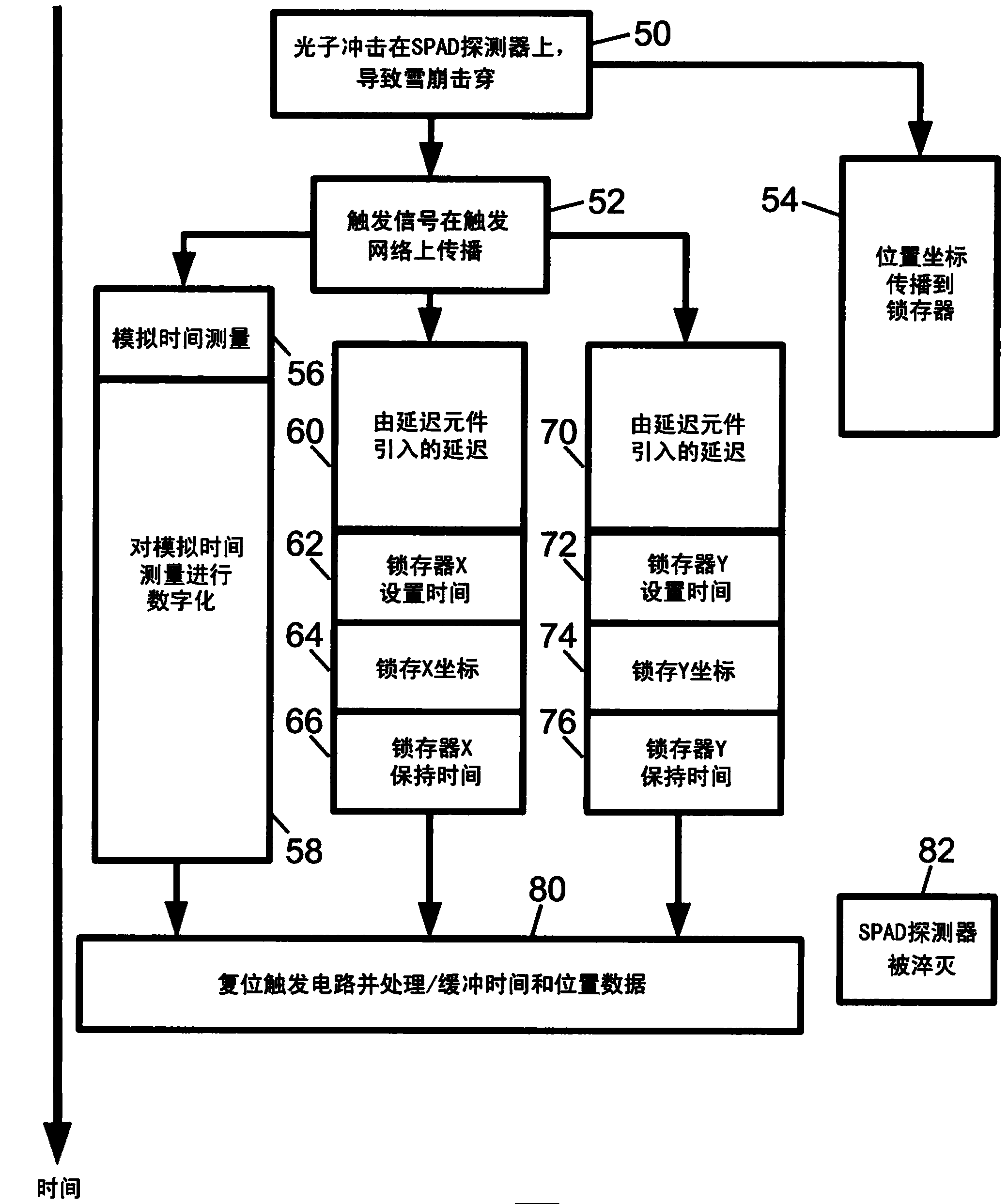
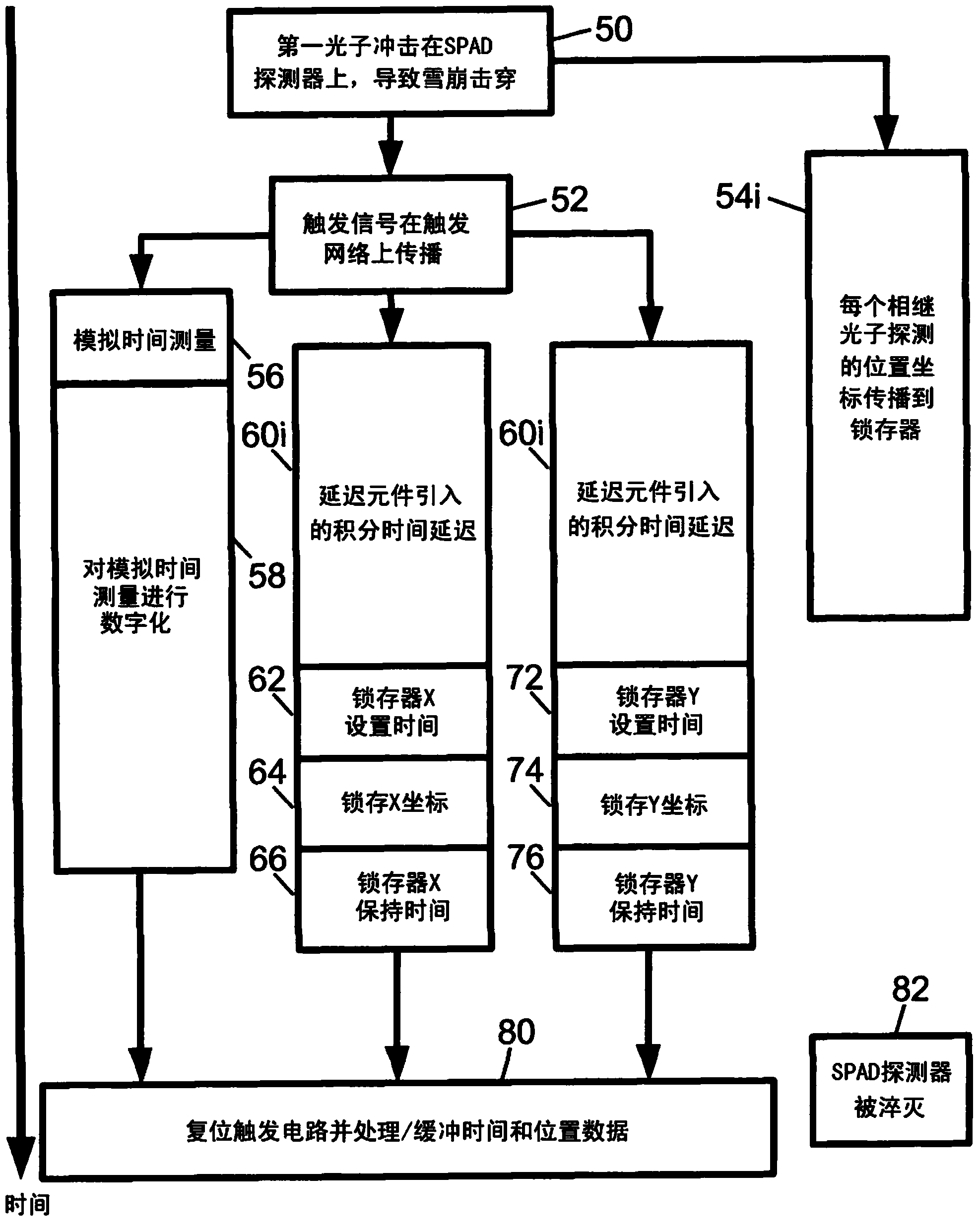
A photon detector (10) includes a detector array (12) comprising single photon avalanche diode (SPAD) detectors (14) configured to break down responsive to impingement of a photon. Trigger circuitry (34) is configured to generate a trigger signal responsive to break down of a SPAD detector of the detector array. Latches (20, 22) are configured to store position coordinates of SPAD detectors of the detector array that are in break down. The latches are configured to latch responsive to a trigger signal generated by the trigger circuitry. The latches may include row latches (22) each connecting with a logical "OR" combination of SPAD detectors of a corresponding row of the detector array, and column latches (20) each connecting with a logical "OR" combination of SPAD detectors of a corresponding column of the detector array. Time to digital converter (TDC) circuitry (28) may generate a digital time stamp for the trigger signal.

Description

technical field [0001] The following relates to radiation detection technology. In particular the invention relates to high speed and high spatial resolution radiation detectors for applications in physics, astronomy, radiation imaging such as positron emission tomography (PET) or single photon emission tomography (SPECT) and the like. Background technique [0002] Photon counting light detection has applications in various fields such as physics, astronomy, and medical imaging. By way of some illustrative examples, photon counting light detection has applications in physics such as Cherenkov detectors, engineering applications such as light detection and ranging (LIDAR) applications, biological applications such as low-light fluorescence measurements, low-light astronomical telescopes It is useful in facilities etc. (As used herein, the term "photon" refers to a quantum particle of electromagnetic radiation. The term "photon" covers photons of visible light, such as the 1...

Claims


Application Information

Patent Timeline
IPC IPC(8): H04N5/369G01T1/24
CPCG01T1/2018G01T1/2985G01T1/248G01T1/249H04N5/369H04N25/70G01T1/20184
Inventor T·弗拉奇
Owner KONINKLJIJKE PHILIPS NV
Learn More