Polishing machine for outer ring end faces of bearings

A technology for bearing outer rings and grinding machines, which is applied to machine tools suitable for grinding workpiece planes, grinding racks, and machine tools suitable for grinding workpiece edges, etc., which can solve the problems of unsatisfactory bearing processing, poor consistency of bearing grinding, Problems such as high labor intensity of workers, to achieve the effect of reducing replacement frequency, preventing pollution, and improving quality

Active Publication Date: 2014-04-23
HAINING QI SHENG BEARING
View PDF6 Cites 37 Cited by
  • Summary
  • Abstract
  • Description
  • Claims
  • Application Information

AI Technical Summary

Problems solved by technology

[0003] The traditional grinding method is to manually hold the bearing close to the desktop grinder to grind the end face of the bearing. The disadvantages are: the labor intensity of the workers is high, and the influence of human factors causes the bearing grinding consistency to be poor; the grinding speed is slow and the efficiency is low

Method used


Image

  • Polishing machine for outer ring end faces of bearings
  • Polishing machine for outer ring end faces of bearings
  • Polishing machine for outer ring end faces of bearings

Examples


Embodiment 1

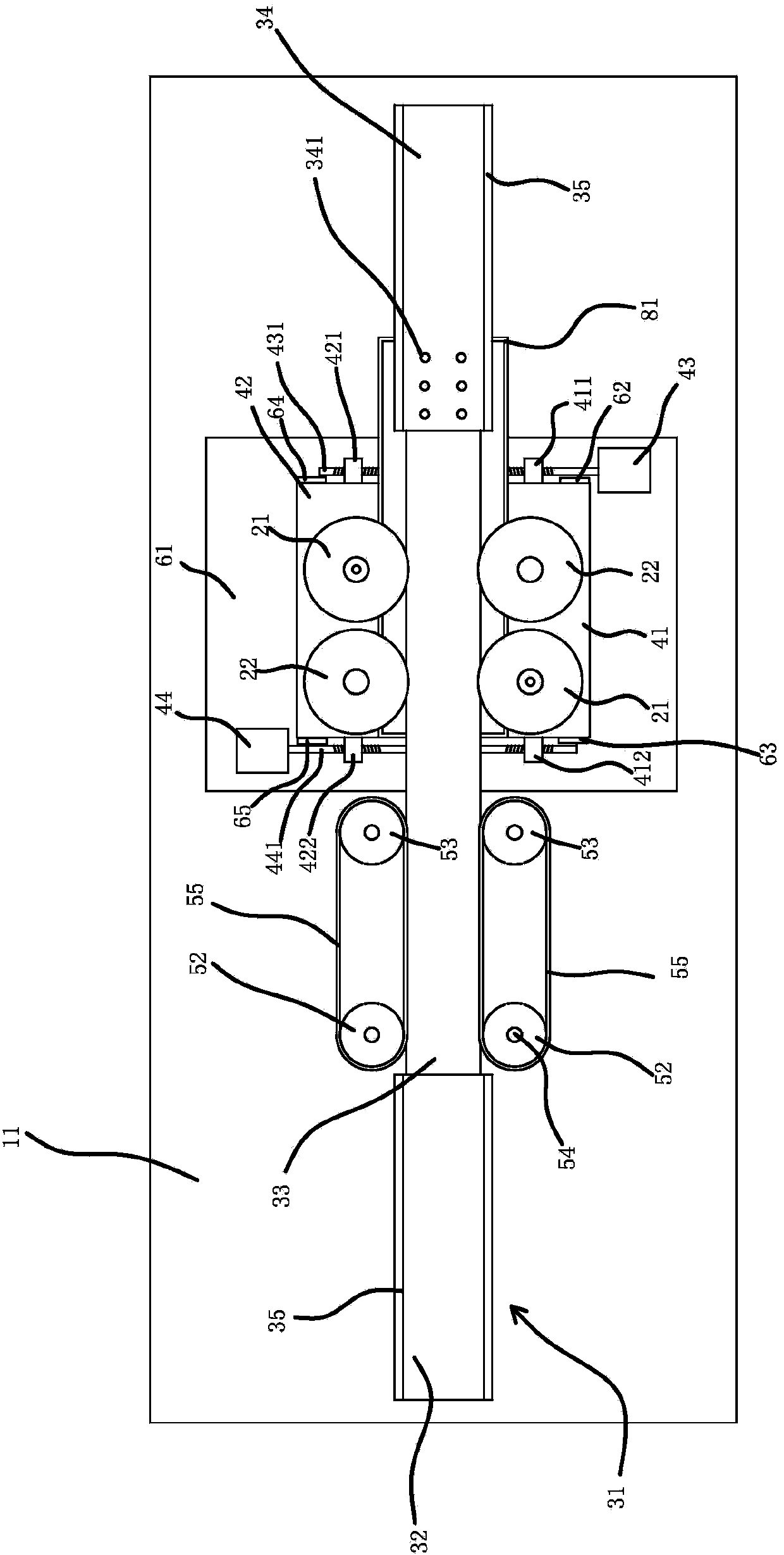
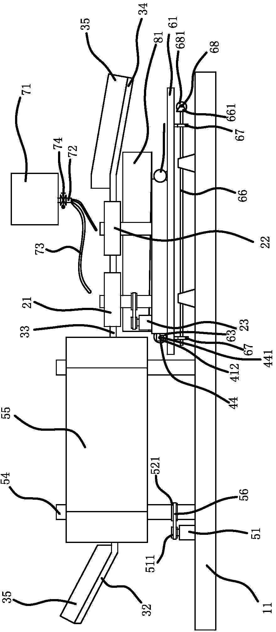
[0027] A grinding machine for the end face of a bearing outer ring, such as figure 1 with figure 2 As shown, the grinding machine comprises a frame 11, a grinding wheel and a guide rail 31, the guide rail 31 is fixed on the frame 11, and the guide rail 31 includes a feeding guide rail 32, a grinding guide rail 33 and a discharge guide rail 34 connected in sequence, and the feeding guide rail 32 All have the baffle plate 35 that is positioned at guide rail 31 both sides on the discharge guide rail 34, the grinding guide rail 33 is horizontally arranged, and the feed guide rail 32 and the discharge guide rail 34 are all inclined relative to the horizontal plane and set downward; Slidingly connected with installation on the frame 11 Plate one 41 and mounting plate two 42, mounting plate one 41 is positioned at grinding guide rail 33 one sides, mounting plate two 42 is positioned at grinding guide rail 33 other sides, and grinding wheel is respectively rotated and connected on mo...

Embodiment 2

[0035] The structure and principle of this embodiment are basically the same as that of Embodiment 1, except that the adjustment mechanism includes several adjustment cylinders, the cylinder body of the adjustment cylinder is fixed on the frame, and the piston rod of the adjustment cylinder is fixed to the base plate. By controlling the periodic expansion and contraction of the piston rod of the adjustment cylinder, the substrate is periodically moved in the up and down direction, thereby realizing the up and down periodic movement of the grinding wheel.


PUM


Abstract

The invention provides a polishing machine for the outer ring end faces of bearings, and belongs to the technical field of machines. The polishing machine solves the technical problems that an exiting polishing machine cannot meet the machining requirement of the bearings in different types, and the application scope is limited. The polishing machine for the outer ring end faces of the bearings comprises a machine frame, a polishing abrasion wheel and a guide rail, the guide rail is fixed on the machine frame, a first installation plate and a second installation plate are connected to the machine frame in a sliding mode, and the polishing abrasion wheel is respectively connected to the first installation plate and the second installation plate in a rotary mode. A first adjusting block and a second adjusting block are fixed on the first installation plate, a third adjusting block and a fourth adjusting block are fixed on the second installation plate, a first adjusting motor and a second adjusting motor are fixed on the machine frame, a first lead screw is fixed on the first adjusting motor and penetrates through the first adjusting block and the third adjusting block, a second lead screw is fixed on the second adjusting motor and penetrates through the second adjusting block and the fourth adjusting block, and a feeding device is further arranged between the polishing abrasion wheel and the feeding guide rail. The polishing machine has the advantages that the bearings in the different types can be polished.

Description

technical field [0001] The invention belongs to the technical field of machinery, and relates to a grinder, in particular to a grinder for the end face of a bearing outer ring. Background technique [0002] After the bearing is manufactured, because there will be different degrees of flashes and burrs on the end surface of the bearing, it needs to undergo treatment processes such as shot blasting and grinding to make the end surface smooth. [0003] The traditional grinding method is to manually hold the bearing close to the desktop grinder to grind the end face of the bearing. The disadvantages are: the labor intensity of the workers is high, and the influence of human factors causes the bearing grinding consistency to be poor; the grinding speed is slow and the efficiency is low, which is not conducive to mass production. [0004] For this reason, Chinese patent literature discloses a grinding machine [CN103128622A], comprising: a frame, a rotary drive assembly, a pressure...

Claims


Application Information

Patent Timeline
IPC IPC(8): B24B7/16B24B55/00B24B55/12
CPCB24B7/16B24B7/17B24B9/04B24B27/0076B24B41/005B24B41/02B24B49/14B24B55/00B24B55/02B24B55/03B24B55/12
Inventor 吕咏奇
Owner HAINING QI SHENG BEARING
Why Eureka
Try Eureka