
Thermal bubble supercharged liquid jet nozzle

A technology of liquid injection nozzles and hot bubbles, applied in fuel injection devices, engine components, machines/engines, etc., can solve the problems of difficult pressure, high production cost, complex structure, etc., and achieve simple and convenient adjustment, simplified mechanical movement, The effect of simple structure

Inactive Publication Date: 2014-04-23
苟仲武
View PDF6 Cites 4 Cited by
  • Summary
  • Abstract
  • Description
  • Claims
  • Application Information

AI Technical Summary

Problems solved by technology

[0003] In order to pressurize the existing technology, there is a high-pressure common rail technology, which connects the ultra-high-pressure pressure circuits to the liquid injection nozzles one by one through different pipelines. However, the whole process has long pipelines, many links, and the pressure is not easy to maintain. The structure is complex, the volume is huge, and the risk in the transmission process is relatively high
[0004] The liquid spray nozzles widely used in the market currently use simple solenoid valves. When the solenoid coil is energized, suction is generated, and the movement of the armature drives the needle valve to be sucked up, thereby opening the nozzle hole, and the liquid passes through the shaft needle on the head of the needle valve. The annular gap between the spray hole and the spray hole is sprayed at high speed to form a mist. This kind of nozzle does not have a pressurization function and can only achieve low-pressure spray, which is difficult to improve the spray effect.
However, the existing liquid spray nozzles with pressurization function have technical problems such as relatively large volume, relatively complicated structure, high production cost, and relatively difficult maintenance.
[0005] There is also a type of expander in the prior art, which is similar to the working principle of the compression ignition power machine. It injects ultra-low temperature liquid air into the cylinder, and the liquid air and the compressed high-temperature gas are fully mixed, and immediately gasify and expand, and start to do work. However, it also has many problems such as ultra-low temperature transmission, spraying in ultra-low temperature environment, and difficulty in adiabatic protection during transmission, and the structure of the system is also relatively complicated.

Method used


Image

  • Thermal bubble supercharged liquid jet nozzle

Examples


Embodiment Construction

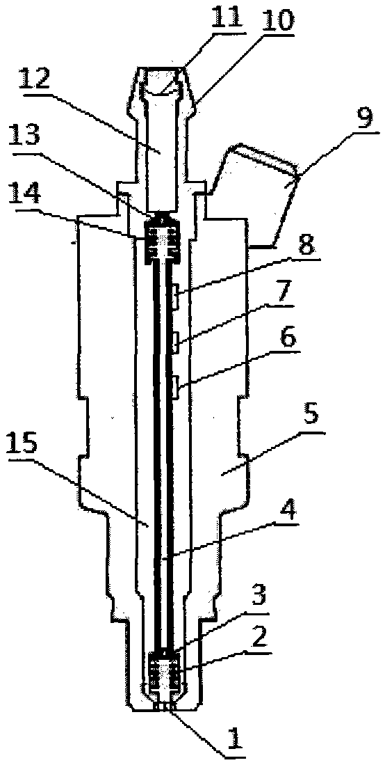
[0026] like figure 1 As shown, a hot bubble pressurized liquid spray nozzle includes a metal shell 5, a nozzle 1, an electrical connector 9, a liquid nozzle 10, a filter screen 11, a thermal insulation plastic layer 15 and a hot bubble pressurized device. The liquid channel in the liquid spray nozzle is connected with the liquid nozzle 10, the hot bubble booster device and the nozzle 1 in sequence from top to bottom, and a filter screen 11 is arranged at the entrance of the liquid nozzle, and a liquid storage area is formed between the hot bubble booster device and the liquid nozzle 12. The thermal insulation plastic layer 15 is arranged in the housing to cover the entire liquid channel.

[0027] The hot bubble pressurization device includes: a liquid spray pipe 4 , a first one-way valve, a second one-way valve, a first electric heating plate 6 , a second electric heating plate 7 , and a third electric heating plate 8 . The first one-way valve is arranged at the inlet of the ...


PUM


Abstract

The invention belongs to the field of liquid jet technologies, and particularly relates to a thermal bubble supercharged liquid jet nozzle which comprises a shell (5), a jet nozzle (1), an electric connector (9), a liquid nozzle (10) and a thermal bubble supercharging device. A liquid channel in the liquid jet nozzle is sequentially connected with the liquid nozzle (10), the thermal bubble supercharging device and the jet nozzle (1) from top to bottom, and a liquid storage zone (12) is formed between the thermal bubble supercharging device and the liquid nozzle; the thermal bubble supercharging device comprises a liquid jet tube (4), a first check valve, a second check valve and heating devices, the first check valve is arranged at an inlet of the liquid jet tube, the second check valve is arranged at an outlet of the liquid jet tube, and the heating devices are arranged on the liquid jet tube. The thermal bubble supercharged liquid jet nozzle has the advantages that the thermal bubble supercharged liquid jet nozzle is simple in structure, low in energy consumption, high in reliability and wide in temperature application range, and low-pressure liquid can be quickly jetted at a high pressure.

Description

technical field [0001] The invention belongs to the technical field of liquid injection, and in particular relates to a hot bubble pressurized liquid injection nozzle. Background technique [0002] The existing compression ignition power machine compresses the gas in the cylinder to one-fifteenth to one-twentieth of its volume through a high compression ratio. Ignition point, the liquid nozzle sprays the liquid with the highest possible pressure and the finest atomized particles, and fully mixes with the compressed high-temperature and high-pressure air for combustion. Since the temperature of the compressed high-pressure gas has exceeded the ignition point of the liquid, the liquid can be Timely and sufficient combustion, so that it expands when heated, the pressure rises sharply, and pushes the piston to do work. Therefore, the better the spray effect of the liquid spray nozzle, the more fully the mixture with the compressed air, and the more thorough the combustion of th...

Claims


Application Information

Patent Timeline
IPC IPC(8): F02M53/06
Inventor 苟仲武
Owner 苟仲武
Learn More