Fracturing pump system and fracturing truck

A technology for fracturing pumps and fracturing trucks, which is applied in the direction of pumps, piston pumps, liquid displacement machines, etc. It can solve the problems of only tens of hours of service life, high requirements for lubrication and cooling, and low suction efficiency. Simplicity, low lubrication and cooling requirements, and improved suction efficiency

Active Publication Date: 2014-04-23
SANY PETROLEUM INTELLIGENT EQUIP CO LTD
View PDF5 Cites 12 Cited by
  • Summary
  • Abstract
  • Description
  • Claims
  • Application Information

AI Technical Summary

Problems solved by technology

[0005] In the crankshaft type plunger pump mentioned above, the stroke is short (such as the stroke of the five-cylinder plunger pump is about 200mm), the number of reversing times is large, the plunger moves frequently, and the life of the wearing parts is short, for example, the valve seat of the fluid end, The service life of valves and valve rubbers is only tens of hours; in addition, the output pressure and flow coverage of this crankshaft plunger pump is relatively narrow. To improve the coverage, it is necessary to replace the liquid end with a different cylinder diameter; in addition, When the plunger changes direction frequently and quickly, the fracturing fluid will be discharged before it is fully sucked in, resulting in low suction efficiency and low work efficiency; in addition, the fracturing pump is integrated with a crankshaft, power input gear, connecting rod, and hydraulic pump. The box body and seat body at the end have complex structure, high manufacturing cost, and inconvenient disassembly and maintenance; in addition, the power input gear rotates at high speed and heavy load, which has high requirements for lubrication and cooling, and it is necessary to arrange a complex lubrication system and corresponding cooling. system

Method used


Image

  • Fracturing pump system and fracturing truck
  • Fracturing pump system and fracturing truck
  • Fracturing pump system and fracturing truck

Examples


Embodiment Construction

[0048] It should be pointed out that the description and sequence of specific structures in this section are only descriptions of specific embodiments, and should not be considered as limiting the protection scope of the present invention. In addition, the embodiments in this section and the features in the embodiments can be combined with each other under the condition of no conflict.

[0049] Please refer to Figure 2 to Figure 5 , the embodiments of the present invention will be described in detail below in conjunction with the accompanying drawings.

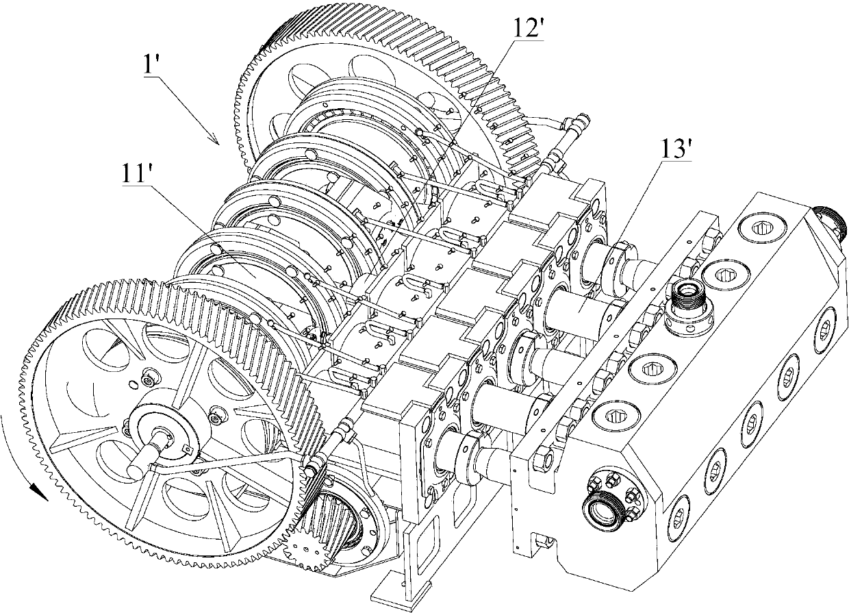
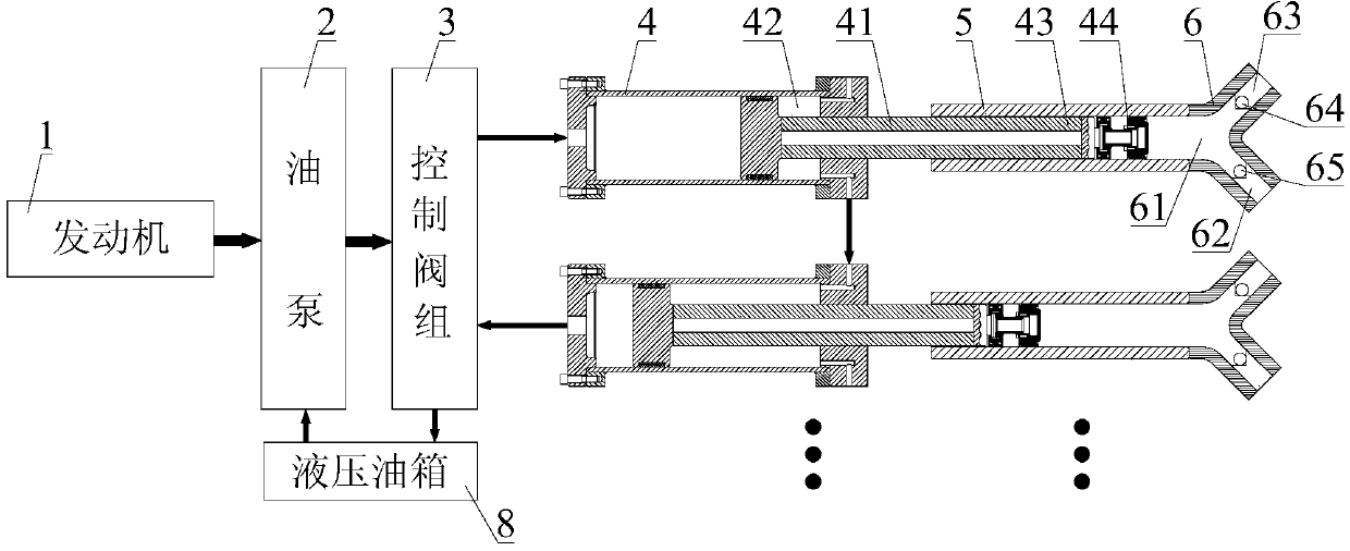
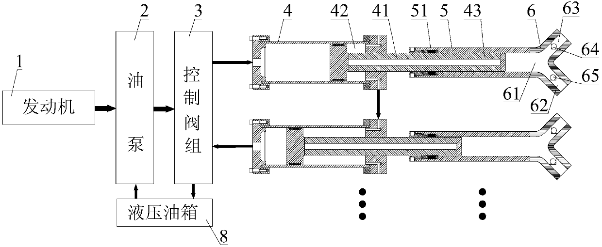
[0050] combine figure 2As shown, the fracturing pump system of the first embodiment of the present invention may include an engine 1, an oil pump 2, a control valve group 3, a hydraulic oil tank 8, a first conveying mechanism and a second conveying mechanism.

[0051] Wherein, the first conveying mechanism and the second conveying mechanism both include an oil cylinder 4, a booster cylinder 5 and a distribution valve 6; th...


PUM


Abstract

The invention discloses a fracturing pump system and a fracturing truck. In the fracturing pump system, a first conveying mechanism and a second conveying mechanism comprise oil cylinders, supercharging cylinders and distribution valves. Each distribution valve comprises a first channel, a second channel and a third channel, wherein the first ends of the first channel, the second channel and the third channel are connected, a suction valve is arranged in the second channel, and a discharge valve is arranged in the third channel. Plug bodies are arranged at the extending end of piston rods of the oil cylinders and movably arranged in the supercharging cylinders, and outlets of the supercharging cylinders are connected with the second end of the first channel. An engine is used for driving an oil pump. A control valve group is used for controlling oil inlet and return states of the oil cylinders. By using the fracturing pump system, a stroke can be effectively increased, stoke times can be decreased, the service life of easily damaged parts can be prolonged, an output pressure and flow coverage range can be effectively widened, the structural complexity can be effectively reduced, the cost can be saved, and the lubrication and cooling requirements can be effectively reduced.

Description

technical field [0001] The invention relates to the technical field of fracturing vehicles, in particular to a fracturing pump system and a fracturing vehicle. Background technique [0002] Fracturing operation is one of the important means to transform oil and gas reservoirs. For low permeability oil and gas wells, it is generally necessary to rely on fracturing operations to achieve the purpose of stabilizing and increasing production. The fracturing vehicle is the main equipment for fracturing construction. Its function is to inject high-pressure and large-volume fracturing fluid into the formation, press the formation apart, and squeeze support materials (such as fracturing sand) into the cracks to strengthen the formation. Permeability, increase oil and gas mobility, enhance oil and gas recovery. [0003] At present, common fracturing vehicles generally include a chassis and a diesel engine, a torque converter, a transmission shaft, and a fracturing pump installed on t...

Claims


Application Information

Patent Timeline
Patent Type & Authority Applications(China)
IPC IPC(8): F04B9/103E21B43/26
Inventor 易小刚
Owner SANY PETROLEUM INTELLIGENT EQUIP CO LTD
Why Eureka
Try Eureka