Floating type multifunctional hydrant for farmland pipeline irrigation

A water supply plug and multi-functional technology, applied in the field of agricultural irrigation, can solve the problems of easy imitation of the open wrench, complex structure, insufficient exhaust volume, etc., and achieve the effect of convenient and fast combined installation, high cost performance and simple structure

Inactive Publication Date: 2014-04-30
PINGYUAN HENGXIN WATER TECH
View PDF11 Cites 21 Cited by
  • Summary
  • Abstract
  • Description
  • Claims
  • Application Information

AI Technical Summary

Problems solved by technology

[0004] One is to stop the water by external pressure and manually close it. Often due to factors such as insufficient closure and excessive pressure, water hammer occurs, causing loosening and water leakage. Before irrigation, it is necessary to check whether it is closed one by one, which is labor-intensive and time-consuming, and management is difficult;
[0005] The second is the lateral water outlet, which can only be installed above the ground, which affects farming and is seriously damaged by agricultural machinery;
[0006] The third is that the opening wrench is easy to imitate, and the phenomenon of random opening and opening is more serious, and it is impossible to irrigate according to the rotation irrigation system;
[0007] Fourth, the function is single, it can only be opened and closed manually, and it cannot realize automatic closing, water metering, air intake and exhaust, protection of pipelines and other comprehensive functions
[0008] Fifth, there are no metering facilities, so it is impossible to realize water metering to households, and it is impossible to realize household charging according to the volume;
[0009] Sixth, most of the protective devices are built on site, which is labor-intensive and time-consuming, and occupies farmland;
The function of the multi-functional water supply cock invented by the above-mentioned patent has been perfected, but the structure is relatively complicated. The main problems are: ①The water stop form of the lower cock body is internal pressure water stop, the water stop valve plate is hemispherical, and the opening and closing depend on The cross support nut inside the lower bolt body and the screw connected to the lower part of the hemispherical water stop valve plate are rotated. When the internal water pressure is large (generally greater than 0.4Mpa), the opening torque is large and it is difficult to open; ②Automatic closing function Relying on the splitter wing on the edge of the hemispherical water stop valve plate to drive the valve plate to rotate counterclockwise under the action of water flow, and then realize the automatic closing function. When the water pressure is relatively small (generally less than 0.01Mpa), due to the slow water flow speed The water stop valve plate rotates, and the automatic closing function cannot be realized; ③The water splitter around the edge of the hemispherical water stop valve plate and the concave structure at the bottom of the hemispherical valve plate cause poor water flow conditions during operation and a large loss of water head. Negative pressure is generated to cause the plug body to vibrate
④Since the inlet and exhaust valves are placed in the ball cavity on the lower side of the top of the hemispherical water stop valve plate, the exhaust holes are small due to space constraints, and the exhaust volume is relatively insufficient. Gas and water are discharged at the same time, causing the bolt to vibrate
At the same time, the air intake effect is relatively poor when the system is closed.

Method used


Image

  • Floating type multifunctional hydrant for farmland pipeline irrigation
  • Floating type multifunctional hydrant for farmland pipeline irrigation
  • Floating type multifunctional hydrant for farmland pipeline irrigation

Examples


Embodiment Construction

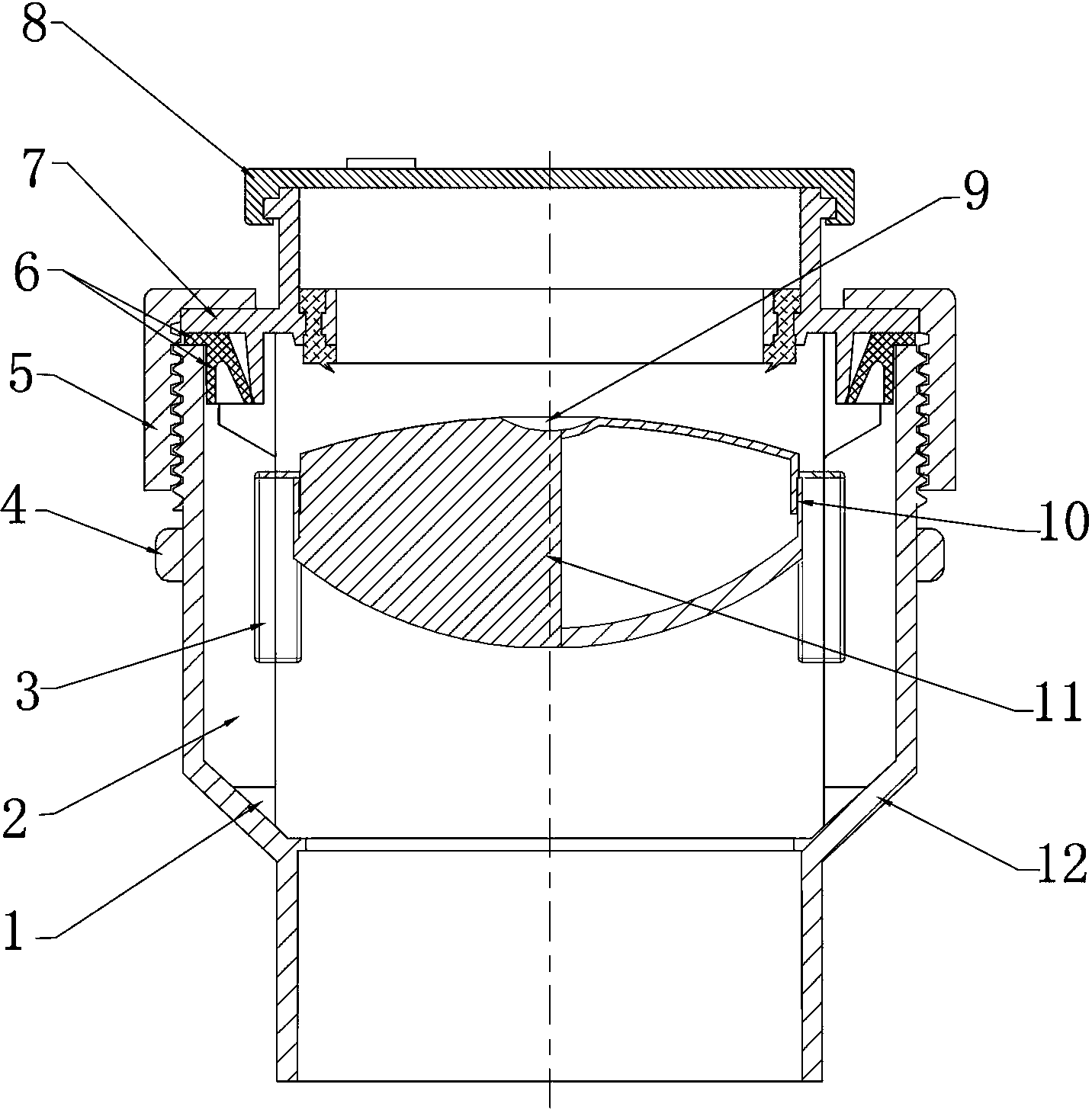
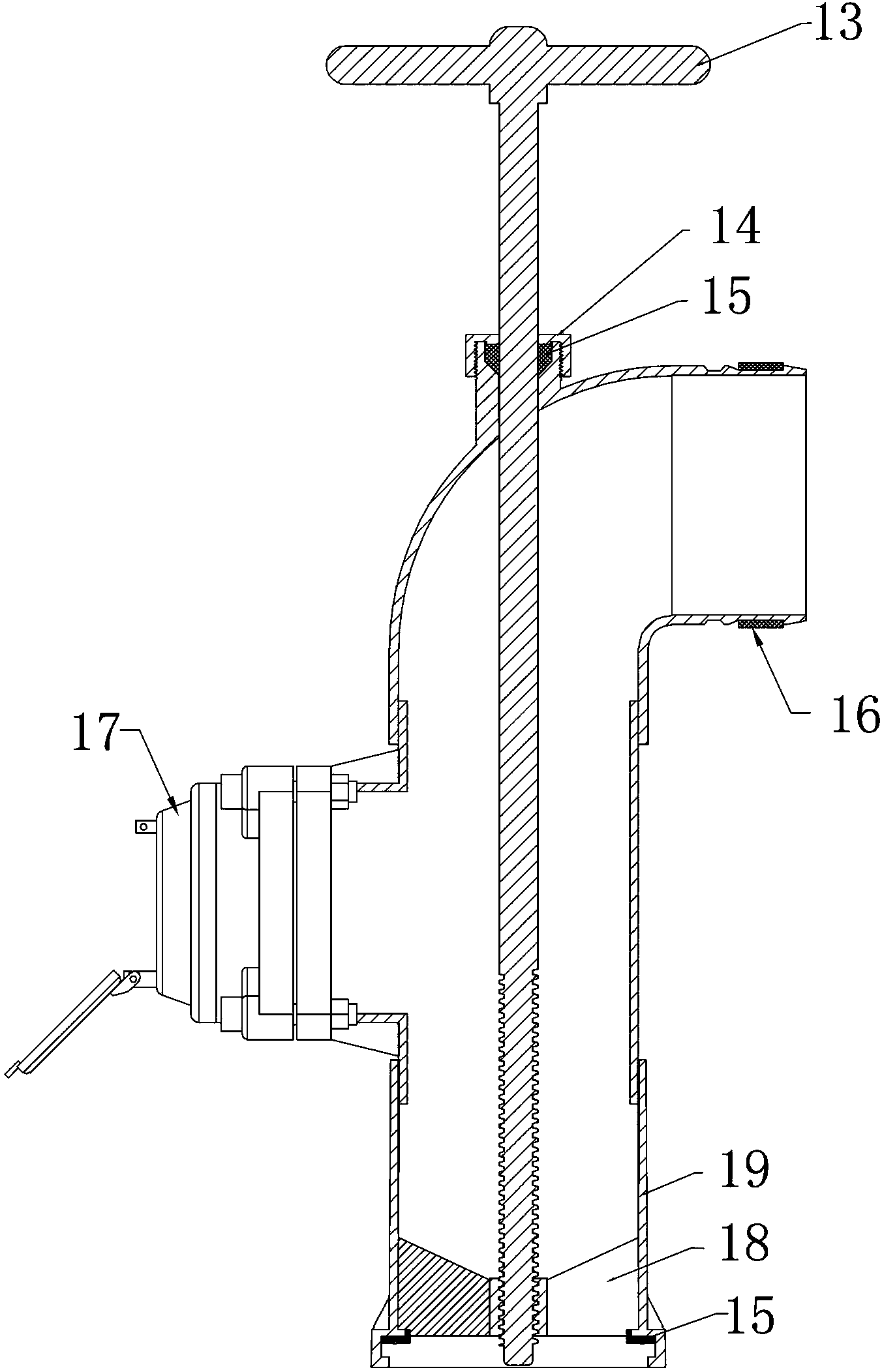
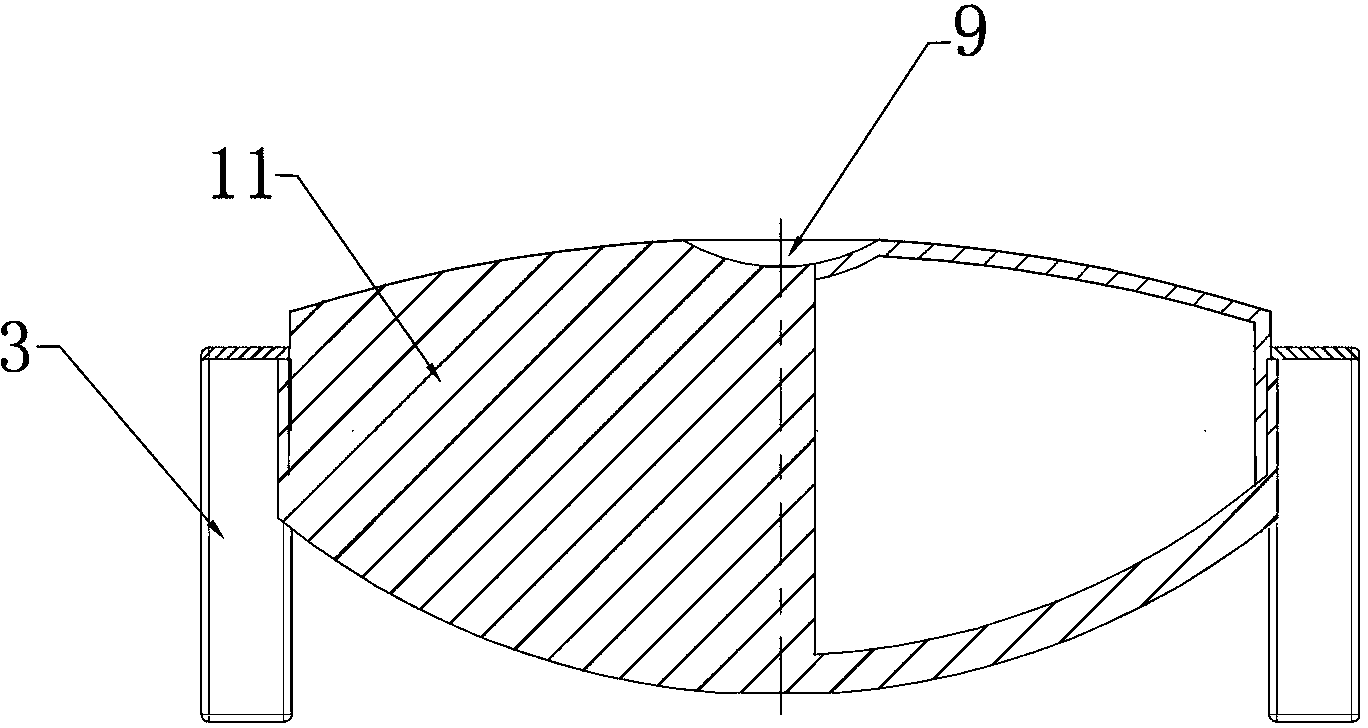
[0038] As shown in the figure: the water supply plug adopts a semi-fixed split combination structure, the lower plug body 12 is fixed below the ground, a floating body type water stop valve 10 is installed inside the lower plug body 12, and the lower plug body 12 is placed in the concrete protection pipe. It is connected with the three-way standpipe of the pipeline to form a fixed device for water supply to the field; the lower plug body 12 adopts the principle of floating body water stop, which realizes the functions of air intake, exhaust, and automatic closing; the upper plug body cooperates with the lower plug body, and the upper plug body The bottom of the body is provided with a cross support rib 18 and an unlatching drive nut 23, forming a special tool for pushing the floating body downward and opening the lower bolt body.

[0039] The lower bolt body is composed of a lower shell, a connecting wire cap, a quick connector, a slideway, a water-stop rubber ring, a floating ...


PUM


Abstract

The invention discloses a floating type multifunctional hydrant for farmland pipeline irrigation. The floating type multifunctional hydrant is mainly composed of an upper hydrant body and a lower hydrant body. The floating type multifunctional hydrant is characterized in that a semi-fixed type split combined structure is adopted in the hydrant, the lower hydrant body is fixed below the ground, a floating type water check valve is arranged in the lower hydrant body, the lower hydrant body is placed in a concrete protective pipe and connected with a pipeline through a three-way vertical pipe to form a fixing device used for supplying water to a farmland; the upper hydrant body is matched with the lower hydrant body. The floating type multifunctional hydrant is simple in structure, convenient and fast to assemble and install, long in service life and high in cost performance. In a non-irrigation season, the lower hydrant body is fixed in the concrete protective pipe below the ground, so the problems that the hydrant affect agricultural machinery cultivation and can be collided and damaged easily are solved. The floating type water stop technology is adopted in the lower hydrant body, and an automatic closing function is achieved through buoyancy of water in the pipeline. The floating type water stop structure has functions of a suction and exhaust valve, and solves the problem that the pipeline is damaged due to water hammer impact and backwater negative pressure.

Description

technical field [0001] The invention belongs to the technical field of agricultural irrigation. Background technique [0002] The water supply hydrant is commonly known as the water outlet. In the pipeline irrigation project, it has important functions such as water delivery and distribution to the ground irrigation system, switch control, water measurement, protection of the pipeline and ensuring irrigation order, so it has become one of the most critical auxiliary facilities in the pipeline irrigation project. [0003] At present, the traditional water supply plugs in engineering practice have mobile, semi-fixed, fixed and other forms of structure. The water-stop structure types include flat valve type, butterfly valve type, ball valve type, wire cover type, etc., and the production materials include cast iron, PE. , PVC, fiberglass, etc., in various forms and materials, there are generally the following six problems: [0004] One is to stop the water by external pressure...

Claims


Application Information

Patent Timeline
IPC IPC(8): A01G25/00F16K27/00
Inventor 宋庆波宋健曹瀚升曹美英郭晓睿
Owner PINGYUAN HENGXIN WATER TECH
Why Eureka
Try Eureka