
Cutting process and device for improving surface brightness of machined metal parts

A metal processing and surface brightness technology, which is applied in metal processing equipment, metal processing machinery parts, measuring/indicating equipment, etc., can solve the problems that the temperature cannot be lowered instantaneously, and the cutting temperature environment cannot be improved, so as to improve the cutting environment and prolong the cutting time. Lifespan, effect of ensuring smoothness

Inactive Publication Date: 2014-04-30
DONGGUAN KONKA MOLD PLASTIC +1
View PDF7 Cites 9 Cited by
  • Summary
  • Abstract
  • Description
  • Claims
  • Application Information

AI Technical Summary

Problems solved by technology

However, it is often overlooked that the temperature in the cutting area suddenly increases with the increase of the tool speed during the cutting process. Because the flow rate value of the coolant and the gas flow rate in the traditional technology are fixed, it is impossible to reduce the temperature in this area instantaneously, and ultimately it is still impossible to solve the problem of improving the cutting temperature. surroundings

Method used


Image

  • Cutting process and device for improving surface brightness of machined metal parts
  • Cutting process and device for improving surface brightness of machined metal parts
  • Cutting process and device for improving surface brightness of machined metal parts

Examples


Embodiment

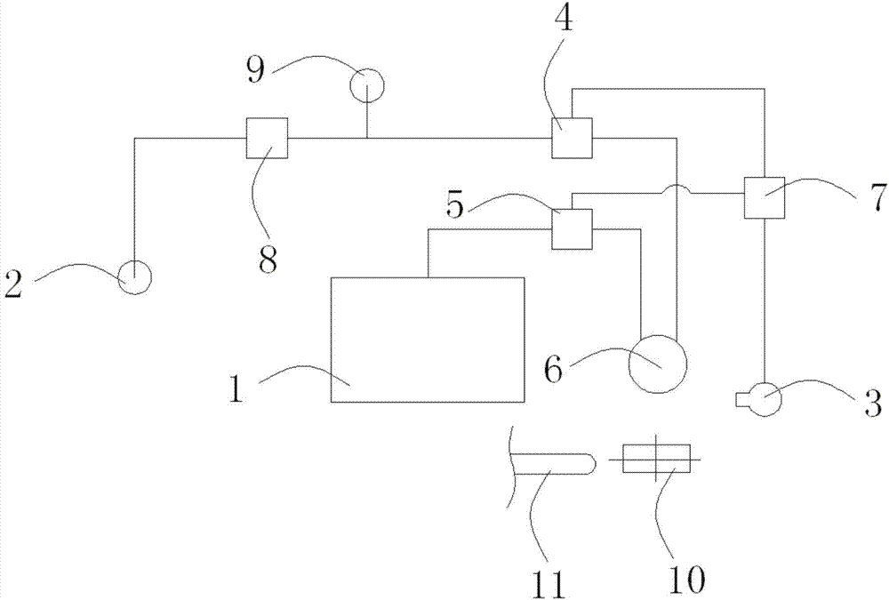
[0040] Example: see figure 1 , the cutting technology that the present embodiment provides to improve the surface brightness of metal processing parts, it comprises the steps:

[0041] (1) A processing machine tool is provided, and the main shaft of the machine tool is provided with a high-pressure oil mist pipe and a cutter head and a nozzle 6 of the central steam hole;

[0042] (2) Set up a high-pressure oil mist compression device, the high-pressure oil mist compression device includes a coolant storage tank 1 and an air compression pump 2, the high-pressure oil mist compression device is connected to the spindle of the processing machine tool; specifically, it also includes:

[0043] A liquid flow controller 5 is installed in the high-pressure oil mist compression device, which receives the control signal of the controller 7 to adjust the coolant flow;

[0044] A gas flow controller 4 is installed in the high-pressure oil mist compression device, which receives the contro...


PUM


Abstract

The invention discloses a cutting process for improving surface brightness of machined metal parts. The cutting process comprises the following steps of arranging a machining machine tool and a high-pressure oil mist compression device; injecting cooling liquid into a cooling liquid storage tank of the compression device and filling compression air into an air compressor pump and delivering mixed high-pressure oil mist into a high-pressure oil mist pipeline of a machine tool spindle through the oil mist compression device after mixing the cooling liquid and the compression air; arranging an infrared sensor in a cutting area and monitoring the temperature change of the cutting area in real time; arranging a workpiece on a working platform of the machining machine tool to be fixed, confirming a machining stroke and parameters according to the three-dimensional size and setting a cutter stroke in the parallel or vertical X-axis / Y-axis direction; starting the machining machine tool and the high-pressure oil mist compression device to spray the towards the cutting area and utilizing triple enhanced heat exchange effects of jet flow impact, air-liquid convection and vaporization to reduce the temperature of the cutting area. The invention further discloses a device implementing the cutting process for improving the surface brightness of the machined metal parts.

Description

technical field [0001] The invention relates to the technical field of mold cutting, in particular to a cutting process and equipment for improving the surface brightness of metal processing parts. Background technique [0002] When cutting metal materials, a large amount of cutting heat will be generated, and its temperature can reach 600-1200°C instantaneously, which will increase the cutting temperature in the cutting area, causing the cutting piece to burn and solidify the sintering and other solidified agglomerates formed on the processed surface. This has a great impact on the surface quality of the workpiece, dimensional accuracy, tool life, kinetic energy consumption, and production efficiency. The entire cutting process becomes difficult, and ultimately affects the surface quality and dimensional accuracy of the workpiece to be processed. [0003] In the current technology, it is often necessary to increase the coolant to cool the cutting during the cutting process,...

Claims


Application Information

Patent Timeline
Patent Type & Authority Applications(China)
IPC IPC(8): B23Q11/10
CPCB23Q11/1015B23Q17/0985Y02P70/10
Inventor 陈旭松胡志兵张巍徐昊
Owner DONGGUAN KONKA MOLD PLASTIC
Learn More