Light emitting diode encapsulating structure

A technology of light-emitting diodes and packaging structures, applied in semiconductor devices, electrical components, circuits, etc., can solve the problems of increased temperature control costs, bulky, inconvenient lamp design, etc., and achieve the effect of improving light output, excellent performance and ingenious design

Active Publication Date: 2014-04-30
GUANGDONG UNIV OF TECH
View PDF6 Cites 8 Cited by
  • Summary
  • Abstract
  • Description
  • Claims
  • Application Information

AI Technical Summary

Problems solved by technology

But at the same time, it will also make the whole system bulky, which is not convenient for

Method used


Image

  • Light emitting diode encapsulating structure
  • Light emitting diode encapsulating structure

Examples


Embodiment

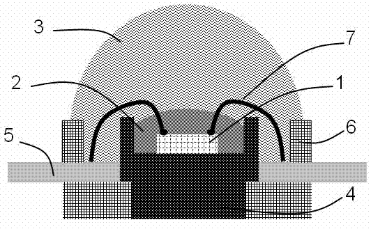
[0012] The structure diagram of the present invention is as figure 1 As shown, the light-emitting diode packaging structure of the present invention includes an LED bracket bowl 4, an LED chip 1 placed on the LED bracket bowl 4, and an LED bracket bowl 4 and an LED chip 1 placed on the LED bracket bowl 4. For potting protection, the LED chip 1 is connected to the LED metal lead wire 7, and the LED bracket cup and bowl 4 is connected to the bracket pin 5, wherein a phase change material is installed between the outside of the LED chip 1 and the outside of the transparent potting material 3 2. The phase change material 2 is a solid at normal temperature, but it is a transparent liquid when the LED chip 1 works stably.

[0013] In this embodiment, the phase change material 2 is poured on the outside of the LED chip 1 , the phase change material 2 seals and wraps the LED chip 1 , and the transparent potting material 3 seals and wraps the phase change material 2 and the LED chip 1 ...

Embodiment 2

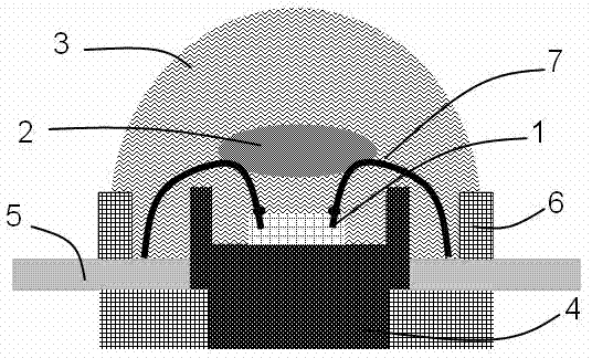
[0024] Embodiment 2 of the present invention is similar to Embodiment 1. The difference between Embodiment 2 of the present invention and Embodiment 1 is that the phase-change material 2, taking paraffin wax as an example, can be sealed and packaged on the premise that the transparent potting material 3 can be guaranteed Next, instead of directly covering the surface of the LED chip 1 , the phase change material 2 is poured into any position between the transparent potting material 3 and the LED chip 1 .


PUM

PropertyMeasurementUnit
Melting pointaaaaaaaaaa

Abstract

The invention discloses a light emitting diode encapsulating structure which comprises an LED support cup, an LED chip placed on the LED support cup, and a phase-change material arranged between the outside of the LED chip and the outside of a transparent encapsulating material and used for encapsulating protection of the LED support cup and the LED chip placed on the LED support cup, wherein the phase-change material is solid at normal temperatures and transparent liquid when the LED chip works stably. According to the light emitting diode encapsulating structure, the phase-change material covers the LED chip serving as a part of the encapsulating material directly, and heat generated when the LED chip works is absorbed by the phase-change material; due to the fact that the phase-change material can absorb a large amount of heat in the phase changing process and the thermal conductivity coefficient and thermal capacity of the phase-change material are higher than those of traditional silica gel and epoxy resin, the juncture temperature of an LED is lower than that when traditional encapsulating materials are used; meanwhile, due to the fact that liquid-phase phase-change material is almost transparent in a visible band and the refractive index is higher than that of traditional encapsulating materials, not only is the juncture temperature of the LED chip reduced, but also the light emitting efficiency of the LED is effectively improved.

Description

technical field [0001] The invention is a light-emitting diode packaging structure, which belongs to the transformation technology of the light-emitting diode packaging structure. Background technique [0002] Light Emitting Diode (referred to as LED) is a solid light emitting device. White LED is known as the fourth-generation lighting source to replace fluorescent lamps and incandescent lamps due to its advantages of high luminous efficiency, no radiation, long life, low power consumption and environmental protection. Power-type light-emitting diodes are more and more widely used in lighting, display, automotive front lights, decoration and other fields. The working power of power LED is usually 1~5 watts, such a large power density will generate a lot of heat inside the chip. If the heat dissipation of the chip and the corresponding packaging structure is not handled well, it will lead to attenuation of LED output light intensity and deterioration of long-term reliabili...

Claims


Application Information

Patent Timeline
IPC IPC(8): H01L33/56H01L33/58
CPCH01L33/56H01L33/641H01L33/644H01L2933/0041H01L2933/0075H01L2224/8592H01L2224/48091H01L2224/48247H01L2224/48465H01L2924/00014H01L2924/00
Inventor 招瑜刘俊魏爱香
Owner GUANGDONG UNIV OF TECH
Why Eureka
Try Eureka