Supercharge Your Innovation With Domain-Expert AI Agents!

Power module

一种功率模块、导体板的技术,应用在操作模式、电动汽车、电动/混合动力等方向,能够解决剥离、绝缘层周围端部龟裂等问题,达到缓和应力、可靠性提高的效果

Active Publication Date: 2014-04-30
HITACHI ASTEMO LTD
View PDF7 Cites 5 Cited by
  • Summary
  • Abstract
  • Description
  • Claims
  • Application Information

AI Technical Summary

Problems solved by technology

However, there is a problem that cracks or peeling occur at the peripheral end of the insulating layer due to the thermal stress caused by the difference in thermal expansion coefficient with the metal conductor plate or the metal base plate.

Method used


Image

  • Power module
  • Power module
  • Power module

Examples


no. 1 approach -

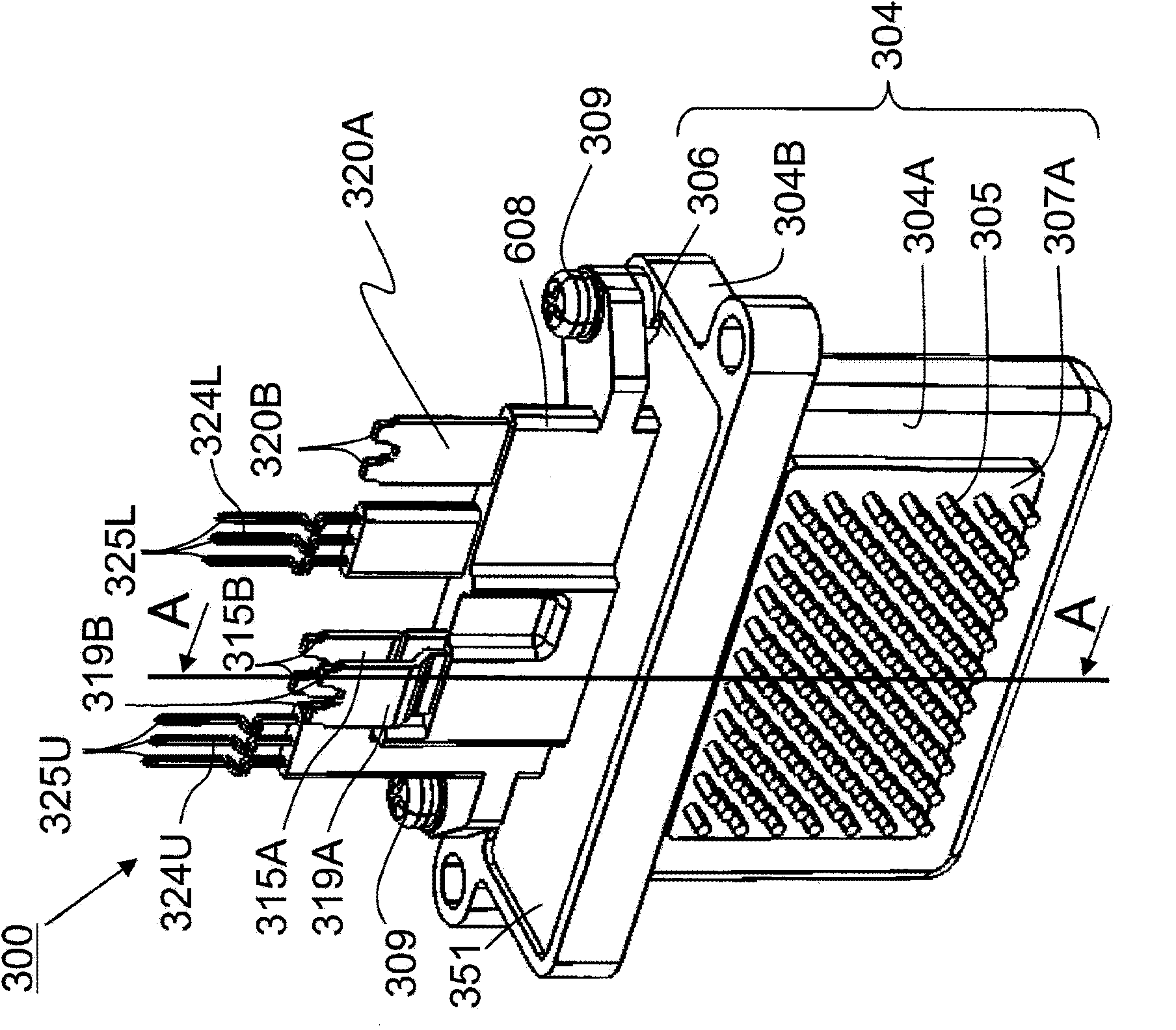
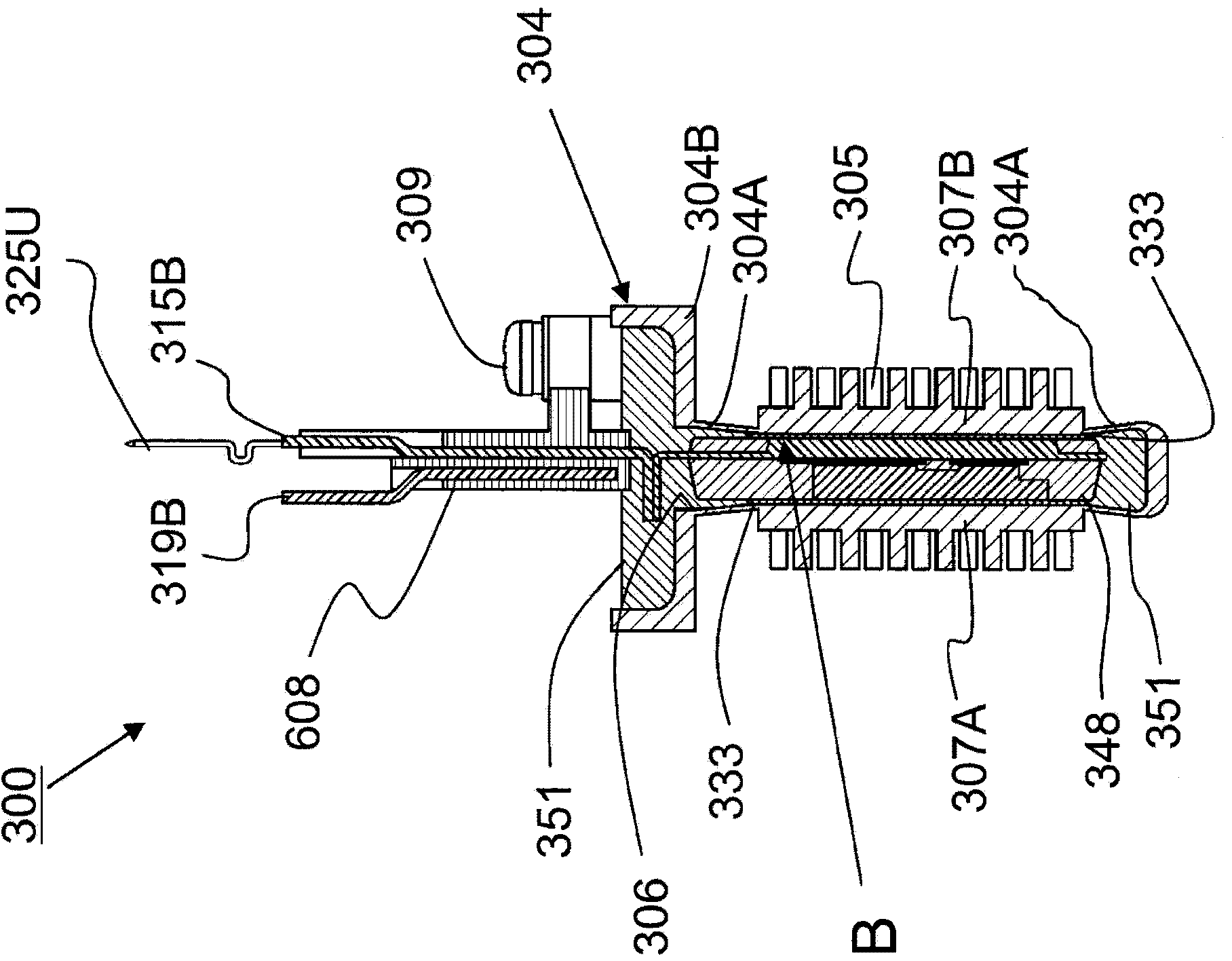
[0064] Figure 1-17 It is a figure which shows 1st Embodiment of the power module of this invention. figure 1 It is a perspective view of the external appearance of the power module. figure 2 yes figure 1 A-A cutaway view. The power module 300 includes switching elements and accommodates a power semiconductor unit of a transfer mold in a module case 304 . The power module 300 can be used, for example, in a power conversion device mounted on an electric vehicle such as an electric car or a hybrid car.

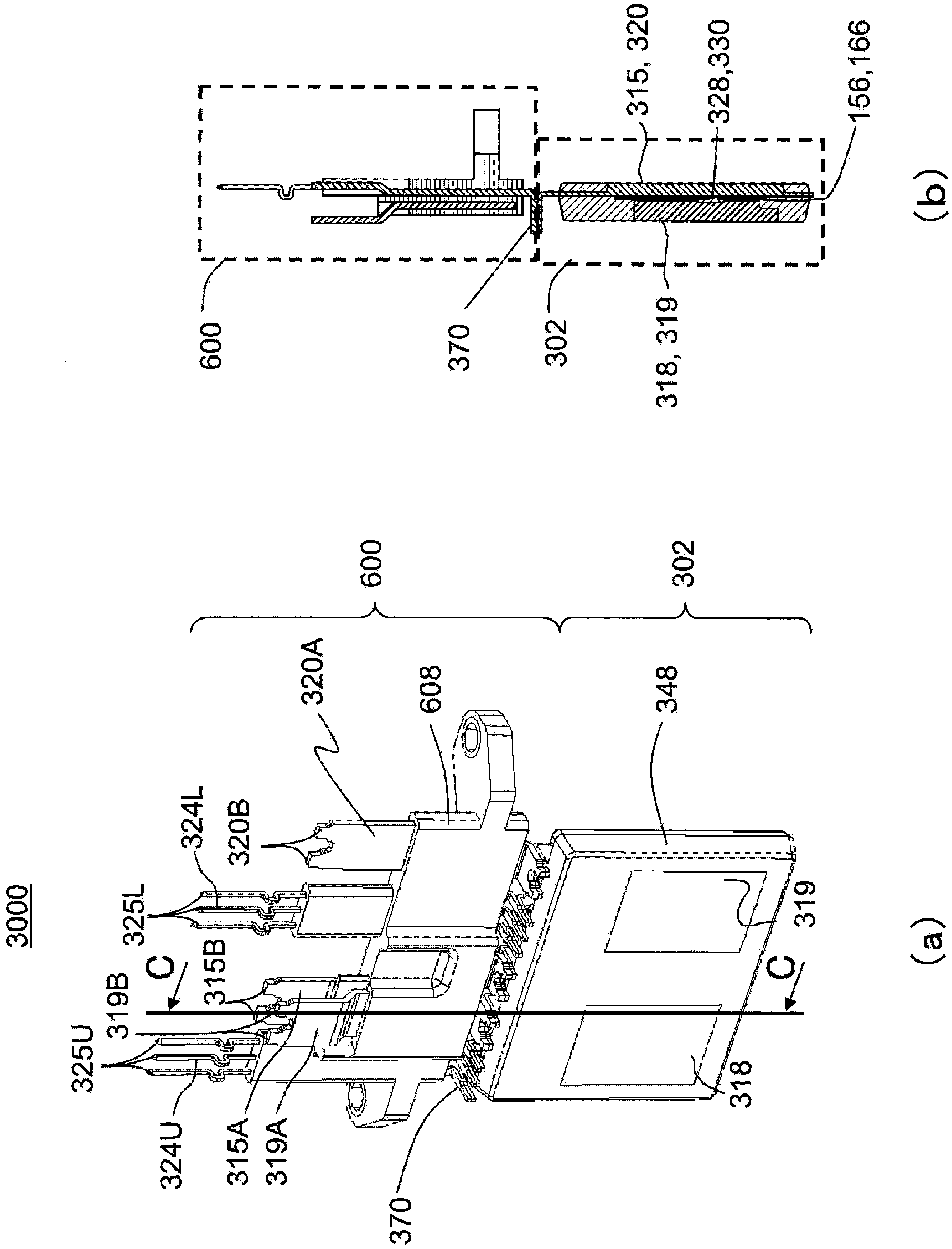
[0065] Such as figure 2 As shown, the power module 300 will image 3 The illustrated power module structure 3000 is housed inside a module case 304 that is a CAN-type cooler. Here, the CAN-type cooler is a cooler formed in a cylindrical shape having an insertion opening 306 on one side and a bottom on the other side. The module case 304 is formed of a member having electrical conductivity, for example, a composite material such as Cu, Cu alloy, Cu—C, Cu—CuO, or a compos...

no. 2 approach -

[0123] Figures 18-21 It is a figure which shows 2nd Embodiment. Figure 18 is a sectional view of the power module. In addition, illustration of the auxiliary mold body 600 of the primary sealing body 302 is omitted. In the first embodiment, the module case 304 is integrally formed, but in the second embodiment, the module case 304 is composed of a case frame and a pair of case side parts. The casing frame is composed of a thick flange 304B and a frame portion 304D. One of the pair of housing side surfaces 304C (the left side in the drawing) is composed of a heat dissipation portion 307A on which a heat dissipation fin 305 is formed, and a thin portion 304A surrounding the periphery thereof. The other case side surface portion 304C is composed of a heat dissipation portion 307B on which the heat dissipation fins 305 are formed, and a thin portion 304A surrounding the periphery thereof. The module case 304 is formed by metal-connecting the thin portion 304A to the case fra...

no. 3 approach -

[0136] Figure 22 It is a figure explaining 3rd Embodiment. As in the above-mentioned second mode, by providing the resin portion 333C with a lower elastic modulus or a higher adhesive force at the peripheral end portion of the laminate composed of the thermal sprayed film 333A and the resin layer 333B, stress concentration on the end portion and peeling can be prevented. Generates and progresses from the end. In the third embodiment, by increasing the amount of resin constituting the resin portion 333C, the effect of alleviating stress concentration is further enhanced.

[0137] exist Figure 22 In the example shown, the resin for impregnation (the same resin as that of the resin portion 333C) overflows a lot, and a straightening band (a portion overflowing from the gap) 333F is formed. In the method of forming the laminated body described in the first embodiment, the amount of resin when impregnated into the sprayed coating 333A is increased so as to protrude more toward ...


PUM


Abstract

A power module provided by the invention is provided with: a sealed body in which a conductor plate on which a semiconductor chip is mounted is sealed by a resin such that a heat dissipating surface of the conductor plate is exposed; a heat dissipating member disposed so as to face the heat dissipating surface; and an insulating layer disposed between the sealed body and the heat dissipating member. The insulating layer has a laminated body which is a lamination of a ceramic thermal spray film impregnated with a resin for impregnation and a resin film for adhesion into which a filler with good thermal conductivity is mixed and which is provided so as to contact the heat dissipating member and at least the entire region of the heat dissipating surface, and a stress relaxation resin part provided in a gap between the heat dissipating member and sealed body so as to cover the entire periphery of the edge parts of the laminated body.

Description

technical field [0001] The present invention relates to a power module excellent in heat dissipation and reliability. Background technique [0002] From the viewpoint of energy saving, electric vehicles driven by electric motors and hybrid vehicles combining electric motor drive and engine drive are attracting attention for automobiles in pursuit of higher fuel consumption. Large-capacity on-board electric motors used in automobiles are difficult to drive or control with the DC voltage of the battery, and a power conversion device using a switch of a power semiconductor element for boosting the voltage and performing AC control is indispensable. In addition, power semiconductor elements generate heat when energized. Therefore, power modules mounted with power semiconductor elements are required to have an insulating layer with a high heat dissipation capability. [0003] For example, as such a power module, there is known a structure in which a laminate is packaged with a r...

Claims


Application Information

Patent Timeline
Patent Type & Authority Applications(China)
IPC IPC(8): H01L23/36H01L25/07H01L25/18B60L50/15B60L50/16
CPCB60L2240/24H05K7/20927B60L2240/421H01L2224/73265H01L24/45H01L2224/48195H01L2224/48137H02M7/003H01L2924/01015Y02T10/7077B60L2250/26H01L2224/48091B60L11/14B60L2240/12B60L2240/423B60L3/003H01L2224/73263H01L2224/8384H01L24/48H01L2224/83801H01L2224/29139H01L2924/1203H01L24/73B60L1/02H01L2224/48472H01L2224/291B60L2240/36H01L2924/01013H01L2224/06181H01L24/34H01L2924/30107H01L24/49H01L2224/4903H01L2224/48247H05K7/209B60L2250/24B60L2260/28H01L21/565H01L23/49524H01L2224/73221H01L23/4334B60L15/007H01L2224/32225B60L2240/525Y02T10/70B60L2220/14B60L2210/40H01L23/473H01L2924/01047H01L2224/04042H01L2224/45124H01L2924/3025H01L23/36H01L2924/13055H01L2924/01028H01L2224/45147H01L23/49575H01L2924/01014B60L15/2036H01L2224/49111H01L2224/40137B60L2250/16B60L2200/42H01L2924/13091H01L2224/49175H01L2224/45014B60L1/003B60L11/123Y02T10/6217H01L2224/48227B60L2200/26H01L2924/1306H01L2924/351H01L2924/181H01L2924/203H01L2924/12042H01L24/40H01L2924/00011Y02P90/60H01L2224/3718H01L2224/37144H01L24/37H01L2224/37124H01L2224/37147H01L2924/00014H01L2224/3716H01L2224/37139H01L2224/37155H01L2224/37157H01L2224/3754H01L2224/371B60L50/61B60L50/16Y02T10/62Y02T10/64Y02T10/72Y02T10/7072H01L2224/72H01L2224/0603H01L2924/00012H01L2924/00H01L2924/014H01L2924/0002H01L2924/01033H01L2224/45099H01L2924/206H01L24/36
Inventor 井出英一西冈映二石井利昭楠川顺平中津欣也诹访时人
Owner HITACHI ASTEMO LTD
Features
  • R&D
  • Intellectual Property
  • Life Sciences
  • Materials
  • Tech Scout
  • Unparalleled Data Quality
  • Higher Quality Content
  • 60% Fewer Hallucinations
Learn More