CO boiler-flue gas denitration reactor integrated unit

A denitrification reactor and combined device technology, applied in chemical instruments and methods, dispersed particle separation, separation methods, etc., can solve problems such as dust ingress, achieve the effects of reducing investment, ensuring thermal efficiency, and improving heat utilization efficiency

Active Publication Date: 2014-05-07
CHINA PETROLEUM & CHEM CORP +1
View PDF7 Cites 3 Cited by
  • Summary
  • Abstract
  • Description
  • Claims
  • Application Information

AI Technical Summary

Problems solved by technology

[0009] Aiming at the deficiencies of the prior art, the present invention provides a denitrification device for denitrification of FCC regeneration flue gas, which aims to solve the problem in the prior art that the dust contained in the flue gas directly enters the denitrification reactor when dealing with high-dust flue gas

Method used


Image

  • CO boiler-flue gas denitration reactor integrated unit
  • CO boiler-flue gas denitration reactor integrated unit

Examples


Embodiment Construction

[0025] The specific scheme and usage of the denitration reactor of the present invention will be further described below in conjunction with the accompanying drawings.

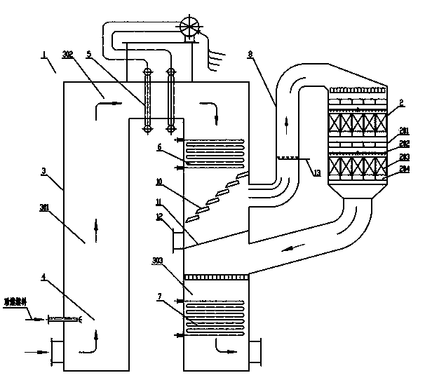
[0026] Depend on figure 1 As shown, the present invention provides a combined device of a CO boiler and a denitration reactor, the combined device includes a CO boiler 1 and a denitration reactor 2, the CO boiler 1 and the denitration reactor 2 are arranged side by side, and the CO boiler includes a flue 3 , combustion chamber 4, steam drum 5, evaporation section 6 and economizer section 7, the flue includes a first vertical flue 301, a horizontal flue 302 and a second vertical flue 303, the horizontal flue Both ends of the duct 302 communicate with the upper part of the first vertical flue 301 and the second vertical flue 303 respectively, the combustion chamber 4 is arranged in the first vertical flue 301, and the steam drum 5 is arranged in the horizontal flue 302 Inside, the evaporation section 6 and the ...


PUM

PropertyMeasurementUnit
angleaaaaaaaaaa
angleaaaaaaaaaa

Abstract

The invention discloses a CO boiler-flue gas denitration reactor integrated unit. According to the CO boiler-flue gas denitration reactor integrated unit, a CO boiler and a denitration reactor are arranged in parallel; the CO boiler comprises a first vertical flue, a horizontal flue, and a second vertical flue; an evaporation zone is arranged on the internal upper part of the second vertical flue; the denitration reactor is communicated with the second vertical flue via an inlet flue and an outlet flue; dedusting grilles are arranged below the evaporation zone, and is opposite to an inlet of the inlet flue of the denitration reactor; a dust collecting plate is slantly arranged below the dedusting grilles; a part of the flue wall near the lowest part of the dust collecting plate is provided with a dust outlet; the outlet flue of the denitration reactor is connected with the second vertical flue below the dust collecting plate; and a coal economizer is arranged below the outlet flue. The CO boiler-flue gas denitration reactor integrated unit is capable of realizing denitration of flue gas without influencing recycling of CO boiler flue waste heat, achieving preferable utilization of flue gas waste heat, increasing heat urilization efficiency, and reducing investment.

Description

technical field [0001] The invention relates to a treatment device for FCC regenerated flue gas in an oil refinery, in particular to a combined device of a CO boiler and a flue gas denitrification reactor for treating the FCC regenerated flue gas in a refinery. Background technique [0002] Nitrogen oxides (NOx) are one of the main sources of air pollution. Nitrogen oxides include compounds such as nitrous oxide (N 2 O), nitric oxide (NO), nitrogen dioxide (NO 2 ), nitrogen trioxide (N 2 o 3 ), dinitrogen tetroxide (N 2 o 4 ) and dinitrogen pentoxide (N 2 o 5 )Wait. Except for nitrogen dioxide, other nitrogen oxides are extremely unstable, and turn into nitrogen dioxide and nitric oxide when exposed to light, humidity or heat, and nitrogen monoxide turns into nitrogen dioxide. Therefore, exposure to several gas mixtures in the occupational environment is often called gunpowder (gas), mainly nitric oxide and nitrogen dioxide, and nitrogen dioxide is the main one. NO...

Claims


Application Information

Patent Timeline
Patent Type & Authority Applications(China)
IPC IPC(8): B01D53/90B01D53/79B01D53/56B01D45/12B01D45/02
Inventor 齐慧敏彭德强姜阳李欣王岩刘杰王明星
Owner CHINA PETROLEUM & CHEM CORP
Why Eureka
Try Eureka