
Drilling and milling carbon fiber composite material follow-up dust collection device

A dust removal device and composite material technology, applied in the direction of dust removal, maintenance and safety accessories, use of liquid separation agent, etc., can solve the problem that dust cannot be fully collected in real time, and achieve the effect of non-destructive fast connection and prevention of floating everywhere

Active Publication Date: 2014-05-07
DALIAN UNIV OF TECH
View PDF6 Cites 37 Cited by
  • Summary
  • Abstract
  • Description
  • Claims
  • Application Information

AI Technical Summary

Problems solved by technology

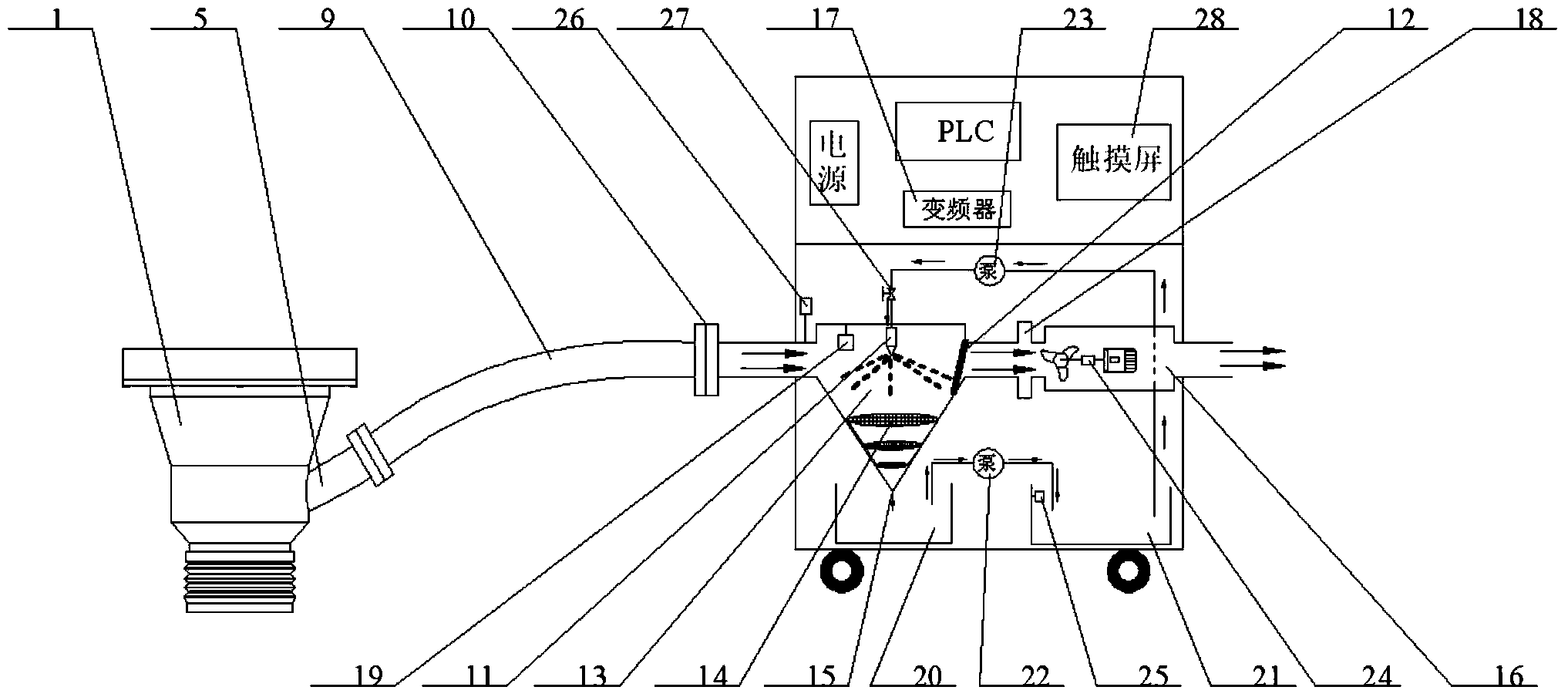
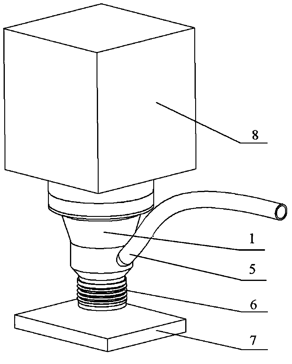
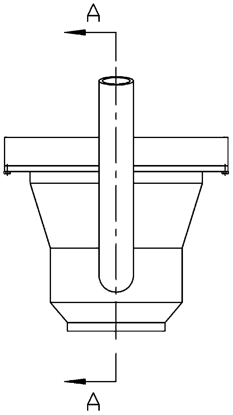
[0004] The technical problem to be solved by the present invention is to solve the current situation that the dust cannot be collected in real time in the process of drilling and milling carbon fiber composite materials, to overcome the deficiencies of the prior art, and to invent a follow-up dust removal device for drilling and milling carbon fiber composite materials. The iron suction cup 3 is a clamping element, which realizes the non-destructive and quick connection and disassembly of the chip collection cover 1 and the special / non-special machine tool spindle box for composite materials; the flexible material is in contact with the workpiece to realize the fully closed and self-adaptive dust removal in the processing process; Concentration transmitter 19 is a sensing element, which detects the concentration of dust in the dust reduction chamber 14; uses photoelectric rotary encoder 24 as a sensing element, detects the speed of high-pressure centrifugal fan 16 when it is running; and uses wind pressure transmitter 26 as a sensing element , detect the pressure in the pipeline when the fan is running; detect the water level of the right water tank 21 with the displacement sensor 25; Reverse; use the PID module in the PLC as the control element to control the output frequency of the frequency converter 17; use the PLC as the control element to control the operation of the upper pump 23 and the lower pump 22; use the PLC as the control element to control the on-off of the solenoid valve 27

Method used


Image

  • Drilling and milling carbon fiber composite material follow-up dust collection device
  • Drilling and milling carbon fiber composite material follow-up dust collection device
  • Drilling and milling carbon fiber composite material follow-up dust collection device

Examples


Embodiment Construction

[0012] The specific implementation of the present invention is described in detail below in conjunction with accompanying drawing and technical scheme, present embodiment a kind of drilling and milling carbon fiber composite material follow-up dedusting device, the frequency converter in this device, PLC, high-pressure centrifugal fan, muffler, dust concentration transmitter , wind pressure sensor, displacement sensor, wet dust collector and water circulation filter device are all installed in the electric control cabinet to realize the online detection, control, adjustment and diagnosis functions of the dust removal system.

[0013] The working principle of the present invention is: the follow-up dust removal device has a chip collection assembly, a wet dust collector, a power part and a water filtration and circulation device, see the attached figure 1 . Fast and non-destructive connection is realized through the electromagnet chuck 3 in the chip collection assembly and the ...


PUM


Abstract

The invention relates to a drilling and milling carbon fiber composite material follow-up dust collection device, belongs to the technical field of energy saving and environmental protection during the processing process of carbon fiber composite materials, and relates to a carbon fiber composite material dust removal and collection device. The device comprises a swarf collecting assembly, a wet process dust-settling device, a power part and a water filtration circulating device. A swarf collecting cover in the swarf collecting assembly is arranged on a machine tool spindle box, and an annular electromagnet sucking disc is positioned in an annular groove at the top of the swarf collecting cover; the device is fixed with bolts through a pressing plate; a power cord of the annular electromagnet sucking disc is connected with an I / O (Input / Output) module of a PLC (Programmable Logic Controller) through a contactor. The drilling and milling carbon fiber composite material follow-up dust collection device can sufficiently collect a great deal of dust during the drilling and milling process of carbon fiber composite material, the swarf collecting cover can synchronously feed along with a spindle tool, and pulls away and collects swarf and dust generated during the processing process in time, so that the swarf and the dust are prevented from floating anywhere to cause environmental pollution and damage to machine tool equipment.

Description

technical field [0001] The invention belongs to the technical field of energy saving and environmental protection in the processing process of carbon fiber composite materials, and relates to a dust removal and collection device for carbon fiber composite material dust. Background technique [0002] Carbon fiber composites will generate a lot of dust during the machining process, which will have adverse effects on the health of on-site personnel; if the dust enters between the kinematic pairs, it will increase friction and aggravate the wear of the kinematic pairs; Floating can easily cause a short circuit in the surrounding electric control system or power grid and cause accidents. [0003] Therefore, it is necessary to collect and process a large amount of dust generated during processing in real time. At present, most of the domestic and foreign countries use fixed or hose adjustable position collection covers for dust treatment. The fixed collection covers are covered in...

Claims


Application Information

Patent Timeline
Patent Type & Authority Applications(China)
IPC IPC(8): B08B15/00B23Q11/00B01D47/06
CPCB01D47/06B23Q11/0046Y02P70/10
Inventor 贾振元殷俊伟宿友亮王福吉杨睿牛斌
Owner DALIAN UNIV OF TECH
Learn More