A solar powered co 2 absorption chiller

An absorption refrigerator and solar energy technology, which is applied in the direction of refrigerators, adsorption machines, energy-saving heating/cooling, etc., can solve the problems that restrict the development of refrigeration technology and the strict requirements of compressors, and achieve compact structure, environmental friendliness, and good application foreground effect

Active Publication Date: 2016-12-21
TECHNICAL INST OF PHYSICS & CHEMISTRY - CHINESE ACAD OF SCI
View PDF4 Cites 0 Cited by
  • Summary
  • Abstract
  • Description
  • Claims
  • Application Information

AI Technical Summary

Problems solved by technology

But using CO 2 As the working fluid of the vapor compression cycle, CO 2 Compressed to a pressure above 10MPa, the requirements for the compressor are very strict, so it also restricts the CO 2 Development of Refrigeration Technology

Method used


Image

  • A solar powered co  <sub>2</sub> absorption chiller
  • A solar powered co  <sub>2</sub> absorption chiller
  • A solar powered co  <sub>2</sub> absorption chiller

Examples


Embodiment 1

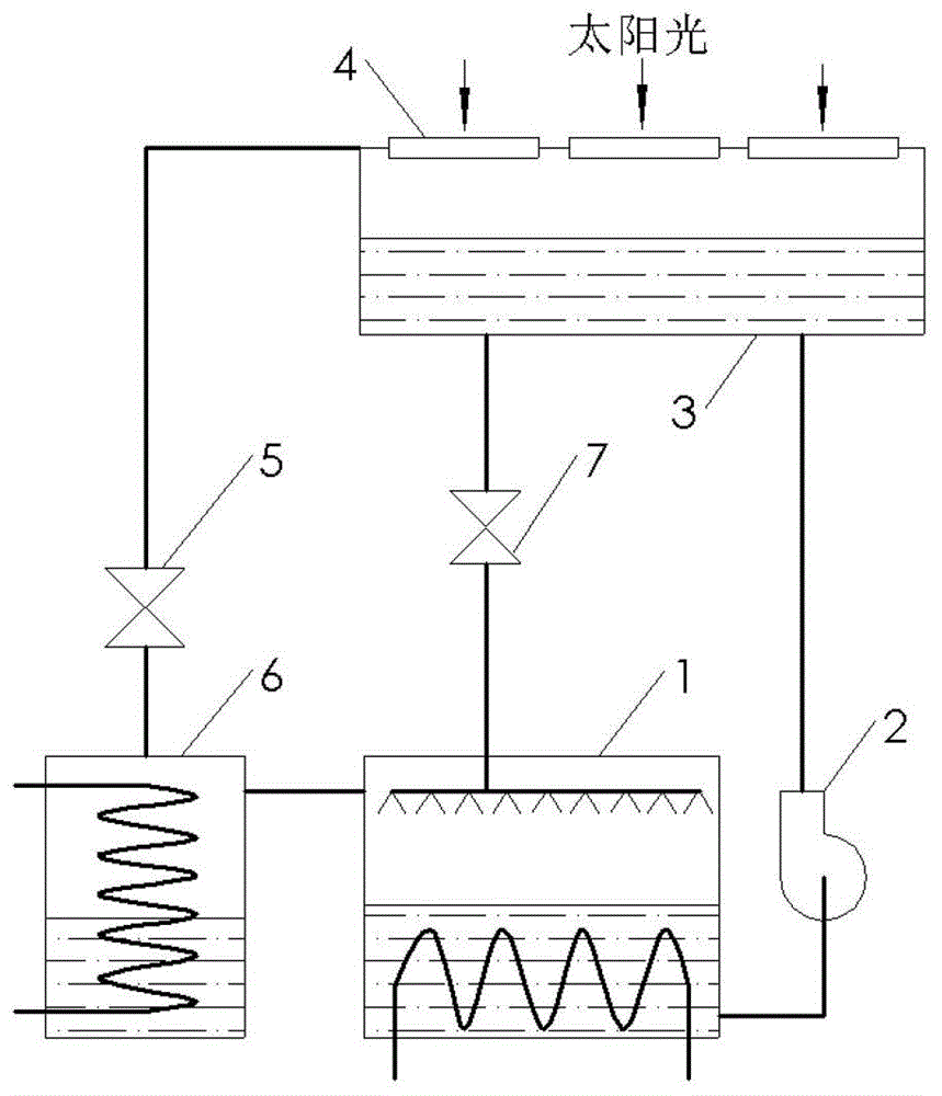
[0029] figure 1 It is a kind of solar-driven CO of the present invention 2 The structural representation of the embodiment 1 of absorption refrigerating machine; As can be seen from the figure, the solar-driven CO of the present embodiment 1 2 Absorption chillers, comprising:

[0030] The absorber 1, the booster pump 2, the solar generator 3, the decompression element 5 and the evaporator 6, which are connected in sequence and form a refrigeration circuit, and the connecting pipe connected between the absorber 1 and the solar generator 3 The flow control valve 7 on the road, the evaporator 6 is connected to the absorber 1; the light-transmitting element 4 is installed on the upper end of the solar generator 3; the inlet of the booster pump 2 is connected to the absorber 1, and the booster pump 2 is connected to the absorber 1 The outlet of the pressure pump 2 is connected to the generator 3; a flowing working medium circulates in the refrigeration circuit; a light-transmitti...

Embodiment 2

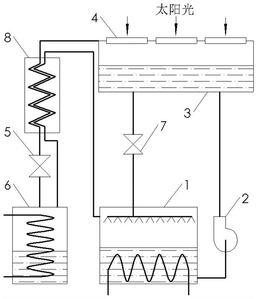
[0033] figure 2 Another solar-driven CO of the present invention 2 Structural schematic diagram of an absorption refrigerating machine (Example 2). It can be seen from the figure that the difference between embodiment 2 and embodiment 1 is that the regenerator 8 is added, that is: the regenerator 8 is installed on the connecting pipeline between the solar generator 3 and the pressure reducing element 5; Both ends of the regenerator 8 are also in communication with the evaporator 6 and the absorber 1 respectively. Because CO 2 The critical point temperature of evaporator 6 is relatively low, and if it is throttled and refrigerated at room temperature, it is difficult to produce a better cooling effect. 2 Flow through the regenerator 8, so that the high-pressure CO 2 The gas is cooled to below room temperature and then decompressed and expanded, so that the CO 2 achieve better cooling effect.

Embodiment 3

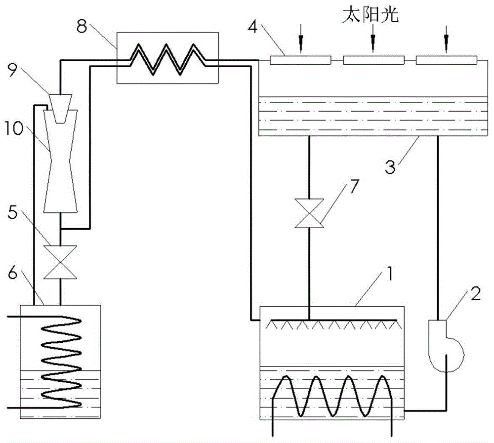
[0035] image 3 Another solar-driven CO of the present invention 2 Schematic diagram of the structure of an absorption refrigerator (Example 3); the structure of this embodiment basically adds a regenerator 8, nozzle 9 and ejector 10 to the structure of Embodiment 1; the regenerator 8, nozzle 9 and ejector The injector 10 is sequentially connected to the connection pipeline between the solar generator 3 and the decompression element 5, and the inlet of the ejector 10 is connected to the evaporator 6; the two ends of the regenerator 8 are also respectively connected to the The decompression element 5 communicates with the absorber 1 . Because the refrigeration efficiency of the simple throttling and decompression process is low, nozzles 9 and ejectors 10 are installed sequentially on the connecting pipeline between the generator 3 and the decompression element 5 in this embodiment; 2 After the gas is cooled by the regenerator 8, it first flows through the nozzle 9, and after ...


PUM


Abstract

A CO2 absorption refrigerator driven by solar energy comprises an absorber, a boosting pump, a solar generator, a pressure reduction element, an evaporator, an absorber and a flow control valve communicated with a connecting pipe between the absorber and the solar generator, wherein the absorber, the boosting pump, the solar generator, the pressure reduction element, the evaporator and the absorber are sequentially connected and form a refrigeration loop, a transmitting element is installed at the upper end of the solar generator, and the evaporator is connected with the absorber. A flowing working medium circulates in the refrigeration loop and is mixed solution composed of CO2 and naphthyridine derivatives. The mixed solution of CO2 and absorbents in the absorber is pressurized through the boosting pump and enters the solar generator; by solar radiation, CO2 is separated from the absorbents and enters the evaporator by pressure reduction of a flow regulator to have refrigeration effect, and the remaining absorbents return to the absorber again; and CO2 absorbs heat and gasified in the evaporator, returns to the absorber again and is dissolved in the absorbents. CO2 is adopted to serve as the working medium of the absorption refrigerator, and the absorption refrigerator is free of toxicity and explosiveness, is high in specific power and environmentally friendly and saves energy.

Description

technical field [0001] The invention relates to a refrigerator in the technical field of refrigeration, in particular to a solar-powered CO 2 Absorption refrigerator. technical background [0002] In nature, CO 2 It is one of the most abundant chemical substances, is part of the atmosphere, and is also contained in some natural gas or associated gas in oil fields and in ores formed by carbonates. CO in the atmosphere 2 0.03~0.04wt%, the total amount is about 2.75×10 12 tons, mainly produced by the combustion of carbonaceous substances and animal metabolism. Therefore, CO 2 It is a natural working substance that will not affect the environment, will not burn and explode, and is extremely easy to obtain. Currently CO 2 The research on refrigerants is mainly concentrated in vapor compression refrigerators. As refrigerants such as Freon gradually withdraw from the historical stage, CO 2 As an excellent refrigerant, it has gradually become a research hotspot in vapor comp...

Claims


Application Information

Patent Timeline
Patent Type & Authority Patents(China)
IPC IPC(8): F25B27/00F25B15/02F25B40/06
CPCY02A30/27Y02B30/62
Inventor 胡剑英罗二仓付文甫
Owner TECHNICAL INST OF PHYSICS & CHEMISTRY - CHINESE ACAD OF SCI
Why Eureka
Try Eureka