Piezoelectric nanometer generator, eyeball moving monitor sensor and monitor method
A nano-generator and generator technology, applied in the direction of generator/motor, sensor, piezoelectric effect/electrostrictive or magnetostrictive motor, etc., can solve the problems of high cost, complex structure, large volume, etc., and achieve Effect of improving bonding fastness, sensitivity and electrical output performance improvement
- Summary
- Abstract
- Description
- Claims
- Application Information
AI Technical Summary
Problems solved by technology
Method used
Image
Examples
Embodiment 1
[0069] Embodiment 1: the preparation of piezoelectric nanogenerator
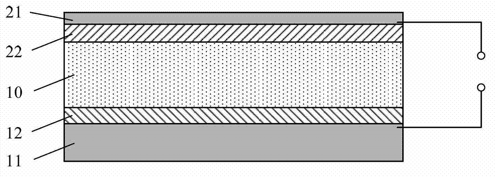
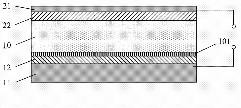
[0070] An aluminum oxide film was grown on an aluminum film with a length of 5 cm x a width of 1 cm x a thickness of 10 microns by anodic oxidation as the first insulating layer, and a zinc oxide seed layer with a thickness of 100 nm was magnetron sputtered on the aluminum oxide film . Then, a ZnO nanowire array with a thickness of about 2 μm is grown on the ZnO seed layer by a hydrothermal method as a piezoelectric material. Then spin-coat a layer of polyparadimethylsiloxane with a thickness of 20 nm on the ZnO nanowire array as the second insulating layer. Finally, an aluminum thin film with a thickness of 50 nm was prepared as the upper electrode layer on the poly(p-dimethylsiloxane) by a deposition method. The structural diagram of the generator can be found in Figure 7 -a, Figure 7 -b is the electron micrograph of the corresponding structure, Figure 7 -d is a partially enlarged view of the seed ...
Embodiment 2
[0072] Embodiment 2: the preparation of piezoelectric nanogenerator
[0073] An aluminum foil with a length of 3 cm x a width of 2 cm x a thickness of 12 microns is used as the lower electrode layer, and a layer of silicon dioxide film is prepared on it as the first insulating layer, and a layer with a thickness of about A thin layer of polyvinylidene fluoride of 1 μm was used as the piezoelectric layer. Then directly deposit an aluminum thin film with a thickness of about 20 nm on the piezoelectric layer as the upper electrode layer. Connect the upper electrode layer and the lower electrode layer to an external voltmeter through a wire, and apply an external force to the generator, such as rubbing or lightly pressing, the voltmeter will output a corresponding electrical signal, indicating that it can convert mechanical energy into electrical energy for power generation.
Embodiment 3
[0074] Example 3: Preparation of eye movement monitoring sensor based on piezoelectric nanogenerator
[0075] A zirconium aluminate film of the first insulating layer with a thickness of 1 μm is grown on an aluminum film with a length of 20 mm x a width of 5 mm x a thickness of 12 microns by anodic oxidation, and then a layer of lead zirconate titanate seed layer is deposited on the film. A layer of lead zirconate titanate nanorod array is grown on the seed layer as a piezoelectric layer by a hydrothermal method, and a layer of polyparadimethylsiloxane is spin-coated on the nanowire array as a second insulating layer. Finally, a layer of copper film is prepared on the poly-p-dimethylsiloxane as the upper electrode layer, and the upper and lower electrodes are connected and drawn out by wires. The device is fixed on the surface of the upper eyelid with adhesive tape, so that the copper film is in close contact with the upper eyelid. When the human eyeball is moving, an obvious ...
PUM
 Abstract
Description
Claims
Application Information
 - R&D
- Intellectual Property
- Life Sciences
- Materials
- Tech Scout
- Unparalleled Data Quality
- Higher Quality Content
- 60% Fewer Hallucinations
Browse by: Latest US Patents, China's latest patents, Technical Efficacy Thesaurus, Application Domain, Technology Topic, Popular Technical Reports.
© 2025 PatSnap. All rights reserved.Legal|Privacy policy|Modern Slavery Act Transparency Statement|Sitemap|About US| Contact US: help@patsnap.com


