Miniature implanted type ultrasonic resonance wireless energy transfer receiver and manufacturing method thereof

A technology of wireless energy and ultrasonic transducers, applied in the direction of microstructure technology, microstructure devices, manufacturing microstructure devices, etc., can solve the problems of adverse effects on human tissue, large volume of piezoelectric materials, and high requirements for ultrasonic pressure, and achieve the realization of Effect of long-term stable energy supply

Active Publication Date: 2014-05-14
SHANGHAI JIAO TONG UNIV
View PDF1 Cites 11 Cited by
  • Summary
  • Abstract
  • Description
  • Claims
  • Application Information

AI Technical Summary

Problems solved by technology

However, due to the large volume of the piezoelectric material used, the ultrasonic pressure and requirements are high, and the ultrasonic medium wave needs to have a higher frequency and sound intensity, which is likely to have adverse effects on human tissues.
At the same time, the sound pressure receiving device and the transmitting device need very high coaxiality, such as the rapid decay of energy transfer efficiency off the central axis

Method used


Image

  • Miniature implanted type ultrasonic resonance wireless energy transfer receiver and manufacturing method thereof
  • Miniature implanted type ultrasonic resonance wireless energy transfer receiver and manufacturing method thereof
  • Miniature implanted type ultrasonic resonance wireless energy transfer receiver and manufacturing method thereof

Examples


Embodiment 1

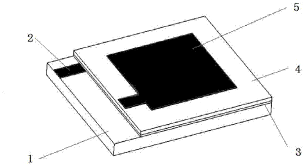
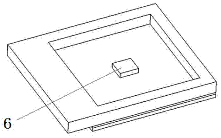
[0058] Such as figure 1 , 2 , 3, in this embodiment, the ultrasonic transducer module 8 is a rectangular piezoelectric material 4 and a rectangular resonant cavity on the back of the corresponding position, and a frequency adjustment mass for adjusting the natural frequency of the device is installed on the inner membrane of the resonant cavity Block 6.

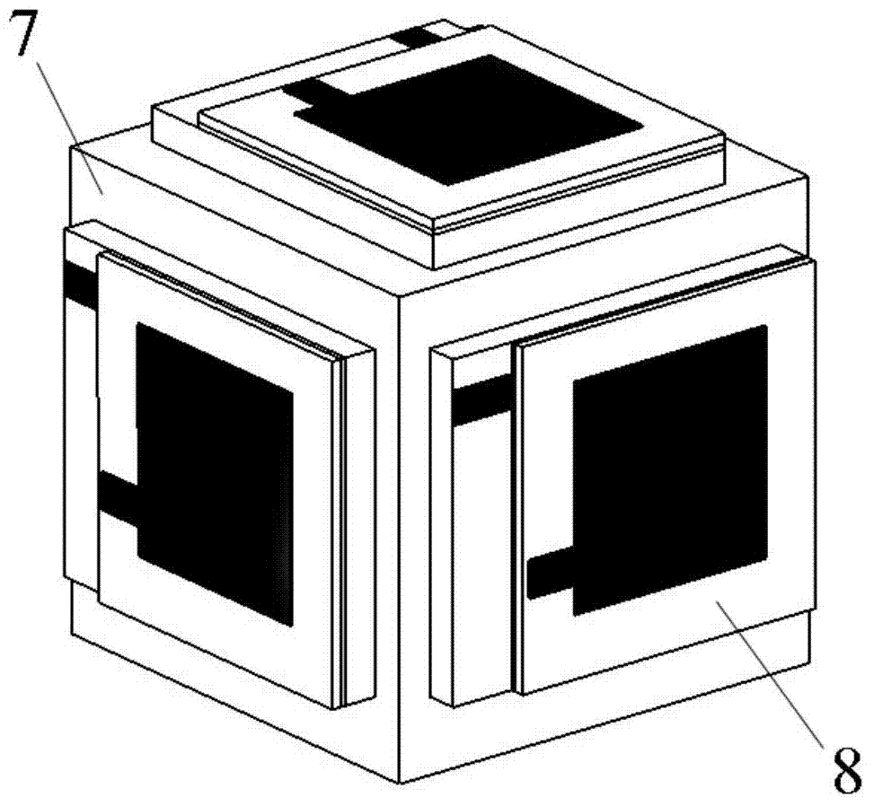
[0059] Such as image 3 As shown, the present embodiment includes a plurality of ultrasonic transducer modules 8 and a polymer structural frame 7 for mounting the ultrasonic transducer modules 8 .

[0060] Such as figure 1 As shown, in this embodiment, the ultrasonic transducer module 8 includes: a silicon substrate 1 (rectangular) with a back cavity, a rectangular piezoelectric material 4 bonded to the silicon substrate 1 through a conductive resin, and upper and lower electrodes Prepared by sputtering (ie bottom metal electrode 2 and top electrode 5). In this example, the overall size of the device is 5±2mm×6±2mm, the ...

Embodiment 2

[0092] Such as Figure 4 , 5 , 6, in the present embodiment, the ultrasonic transducer module 8 adopts a circular piezoelectric material 4 and a corresponding circular resonant cavity, and a frequency adjustment mass with the natural frequency of the adjustment device is pasted in the resonant cavity 6.

[0093] Such as Figure 4 As shown, the overall size of the ultrasonic transducer module 8 in this embodiment is 5±2mm×6±2mm, the thickness is 500±200μm, and the diameter of the resonant cavity is 4mm; 20μm, piezoelectric material 4 film diameter 5±2mm, thickness 40±20μm; such as Figure 5 As shown, the frequency adjustment mass 6 is a columnar nickel alloy with a size of 0.5±0.2mm in diameter and 4±2mm in height; Figure 6 As shown, the polymer structural frame 7 is a trapezoidal boss structure with a height of 2±1 mm, made of PDMS material, but not limited to this material.

[0094] In this embodiment, the ultrasonic transducer module 8 is assembled into a trapezoidal b...

Embodiment 3

[0124] Such as Figure 7 , 8 , 9, in this embodiment, the ultrasonic transducer module 8 adopts a circular piezoelectric material and a corresponding circular resonant cavity.

[0125] Such as image 3 As shown, the ultrasonic transducer module 8 in this embodiment is 5±2×6±2mm, the thickness is 500±200μm, and the diameter of the resonant cavity is 3±1mm; Figure 8 As shown, the silicon substrate has a margin of 40±20 μm after etching the resonant cavity, and the piezoelectric material 4 film has a diameter of 4±1 mm and a thickness of 40±20 μm; Figure 9 As shown, the polymer structural frame 7 is a rectangular structural support with a thickness of 2±1 mm, made of PDMS material, but not limited to this material.

[0126] In this embodiment, the ultrasonic transducer module 8 is assembled on both sides of the rectangular bracket, and its inner center is filled with medical gel. This structure is mostly used for implanting in relatively small parts, such as palms or wrists....


PUM

PropertyMeasurementUnit
Thicknessaaaaaaaaaa

Abstract

The invention relates to a miniature implanted type ultrasonic resonance wireless energy transfer receiver and a manufacturing method of the miniature implanted type ultrasonic resonance wireless energy transfer receiver. The receiver is composed of an ultrasonic transducer module and a supporting frame. By means of the ultrasonic transducer module, piezoelectric materials are bonded on a silicon substrate in an electric conduction mode, the thickness of a piezoelectric film is controlled through a fine mechanical polishing technology, a resonance cavity coupled with the piezoelectric film is manufactured in the back face of the silicon substrate through an etching method, and different ultrasonic frequencies are matched by controlling the thickness of the piezoelectric film and the parameters of the silicon resonance cavity. The supporting frame is a three-dimensional hollow frame formed by pouring biocompatible materials and is used for installation of the ultrasonic transducer module, and dead-angle-free ultrasonic energy transmission in vivo can be achieved by installing resonance sheets on frames of different appearance structures. Wireless energy supply in vitro of an electronic device implanted into the human body can be achieved through the miniature implanted type ultrasonic resonance wireless energy transfer receiver, the effects of implantation depth of the device in vivo on the energy transmission scheme are small, and the miniature implanted type ultrasonic resonance wireless energy transfer receiver does not harm to the human body and has no requirement for transmitting terminal position alignment.

Description

technical field [0001] The invention relates to an implantable micro device, in particular to a miniature implantable ultrasonic resonance wireless energy transmission receiver and a preparation method thereof. Background technique [0002] Implantable medical devices (IMDs) refer to miniature medical electronic devices embedded in the human body, and it is one of the fastest-growing branches of biomedical technology. However, with the popularization of the application of IMDs, the mismatch between the service life of long-term implantable devices and the life span of patients has become the main factor restricting the development of implantable devices. The main factor that restricts the life of implanted devices is the supply of energy. At present, the most widely used method in the world is to use battery integration. However, the volume (miniature) of some devices limits the application of batteries and the attenuation of the energy of the batteries themselves. It also ...

Claims


Application Information

Patent Timeline
IPC IPC(8): H02N2/18B81B3/00B81C1/00
Inventor 刘景全何庆杨斌杨春生
Owner SHANGHAI JIAO TONG UNIV
Why Eureka
Try Eureka