A device and method for desulfurization and refining of liquefied gas in an oil refinery

A technology for liquefied gas and oil refinery, which is applied in the field of liquefied gas desulfurization and refining equipment in oil refineries, can solve the problems of blockage of trays or packing, large fluctuation of hydrogen sulfide and high COD, and achieves the effect of reducing consumption and large contact area

Active Publication Date: 2016-07-13
CHINA PETROLEUM & CHEM CORP
View PDF5 Cites 2 Cited by
  • Summary
  • Abstract
  • Description
  • Claims
  • Application Information

AI Technical Summary

Problems solved by technology

[0004] At present, refineries usually use N-methyldiethanolamine (MDEA) solvent to remove hydrogen sulfide in the extraction tower, and use two-stage alkali washing to remove mercaptans. Due to the miscellaneous sources of liquefied gas, especially catalytic, The liquefied gas produced by the coking unit contains coke powder. In the process of dehydrogenation of liquefied gas with MDEA solvent in the extraction tower, it is easy to cause blockage of the tray or packing. On the one hand, the effect of removing hydrogen sulfide in the liquefied gas is reduced. The hydrogen sulfide in the liquefied gas at the top of the tower fluctuates greatly, far exceeding no more than 20mg / m 3 On the other hand, the liquefied gas at the top of the extraction tower entrains the MDEA solvent to the liquefied gas alkaline cleaning system, resulting in high COD in the alkali slag, which makes the subsequent neutralization of the alkali slag and water dehydration The activity of the activated sludge treated by the treatment unit decreases, which affects the water quality discharge of the refinery

Method used


Image

  • A device and method for desulfurization and refining of liquefied gas in an oil refinery

Examples


Embodiment Construction

[0017] The present invention will be further described below in conjunction with the accompanying drawings and embodiments.

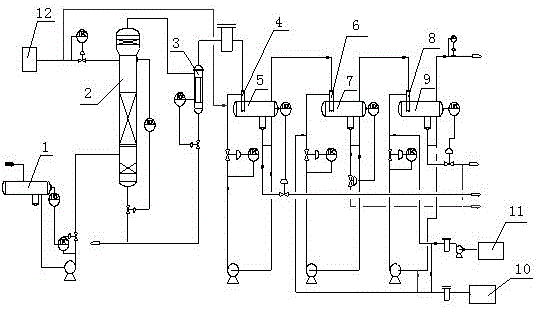
[0018] Such as figure 1 as shown, figure 1 It is a schematic diagram of the liquefied gas desulfurization and refining device of the present invention. The liquefied gas desulfurization and refining device of the present invention includes a buffer tank 1, an extraction tower 2, an MDEA solvent storage tank 12, an alkali storage tank 10, a water storage tank 11, and a primary extraction tank. Extraction settling tank 5, secondary extraction settling tank 7 and tertiary extraction settling tank 9, the outlet of buffer tank 1 is connected to the bottom inlet of extraction tower 2, and the top outlet of extraction tower 2 passes through coalescer 3 and primary fiber membrane The contactor 4 is connected to the primary extraction and settling tank 5, and the MDEA solvent storage tank 12 is respectively connected with the upper inlet of the extraction tower...


PUM


Abstract

The invention relates to a liquefied gas desulfurization refining device in an oil refinery. The device comprises a buffer tank, an extraction tower, an MDEA (methyldiethanolamine) solvent storage tank, an alkaline liquor storage tank, a water storage tank, a primary extraction settling tank, a secondary extraction settling tank and a tertiary extraction settling tank, wherein the outlet of the buffer tank is connected with the bottom inlet of the extraction tower; the top outlet of the extraction tower is connected to the primary extraction settling tank by virtue of a coalescer and a primary fiber membrane contactor; the MDEA solvent storage tank is respectively communicated with the upper outlet of the extraction tower and the primary fiber membrane contactor; a top outlet of the primary extraction settling tank is connected to the secondary extraction settling tank by virtue of a secondary fiber membrane contactor; the top outlet of the secondary extraction settling tank is connected to the tertiary extraction settling tank by virtue of a tertiary fiber membrane contactor; the alkaline liquor storage tank is respectively communicated with the secondary fiber membrane contactor and the tertiary fiber membrane contactor; the water storage tank is communicated with the tertiary fiber membrane contactor. According to the device, when the liquefied gas is subjected to desulfurization refining, the desulfurization effect is good, the consumption of the solvent and alkaline liquor is low, and the cost is greatly saved.

Description

technical field [0001] The invention relates to a device and method for desulfurizing and refining liquefied gas in an oil refinery, which is an improvement to the existing desulfurizing and refining method for liquefied gas in an oil refinery. Background technique [0002] Refinery liquefied gas mainly comes from catalytic cracking, delayed coking, atmospheric and vacuum, hydrocracking, continuous reforming and other devices. Its main components are C3 and C4 hydrocarbons, containing a small amount of C2 and C5 hydrocarbons, and Contains hydrogen sulfide (about 0.01~4%), mercaptan (about 1~9000mg / m 3 ), sulfide (0~100mg / m 3 ), COS and other sulfides. [0003] Due to different sources and components of refinery liquefied gas, the content of various sulfides varies greatly, but mainly hydrogen sulfide and mercaptan. The liquefied gas of atmospheric and vacuum, hydrocracking, and continuous reforming units has less olefin content, and most of them are saturated hydrocarbons...

Claims


Application Information

Patent Timeline
Patent Type & Authority Patents(China)
IPC IPC(8): C10G70/00
Inventor 周建文
Owner CHINA PETROLEUM & CHEM CORP
Why Eureka
Try Eureka