Ammonia torch burner

A technology of torch combustion and ammonia gas, applied in the direction of burners, gas fuel burners, combustion methods, etc., can solve the problems of head corrosion resistance, poor high temperature resistance, poor mixing degree, high maintenance cost, etc., and increase the service life , ensure full combustion, and avoid environmental problems

Inactive Publication Date: 2014-05-21
杜建吉
View PDF6 Cites 6 Cited by
  • Summary
  • Abstract
  • Description
  • Claims
  • Application Information

AI Technical Summary

Problems solved by technology

[0002] The existing ammonia torch burner adopts a straight-through structure, the flame spreads and burns on the burner, the degree of mixing with the air is poor, and the combustion is insufficient, resulting in environmental pollution problems; the head is poor in corrosion resistance and high temperature resistance, resulting in maintenance high cost

Method used


Image

  • Ammonia torch burner
  • Ammonia torch burner

Examples


Embodiment Construction

[0018] In order to facilitate the understanding of the technical content of the present invention, the technical solutions of the present invention will be further described below in conjunction with the accompanying drawings.

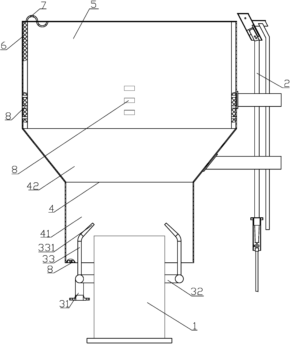
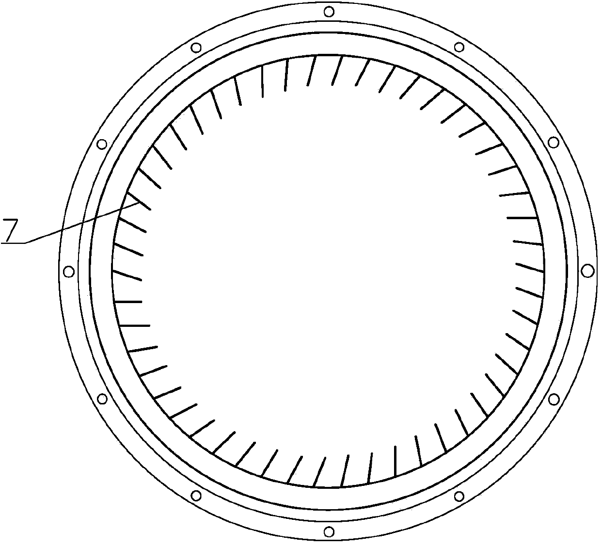
[0019] Such as figure 1 and figure 2 As shown, an ammonia gas torch burner includes an air intake cylinder 1 , an ignition lamp assembly 2 , a fuel gas delivery part, a premixing chamber 4 and a combustion chamber 5 . The intake cylinder 1, the premix chamber 4 and the combustion chamber 5 are coaxially arranged.

[0020] The pre-mixing chamber 4 includes a mixing chamber 41 and an enlarged diameter chamber 42 arranged at the upper end of the mixing chamber 41 and communicating with it. The mixing chamber 41 and the expanding diameter chamber 42 are also arranged coaxially. When the gas enters the diameter-expanding chamber 42 from the mixing chamber 41, the flow velocity slows down and begins to diffuse, which can further ensure the mixing uniform...


PUM


Abstract

The invention relates to an ammonia torch burner which comprises a gas inlet barrel, a pilot burner ignition assembly, a fuel gas conveying part, a premixer and a combustion chamber. The premixer comprises a mixing cavity and an expanded cavity which is formed at the upper end of the mixing cavity and is communicated with the mixing cavity; the mixing cavity is formed at the upper end of the gas inlet barrel and is communicated with the gas inlet barrel; the upper end face of the gas inlet barrel extends into the mixing cavity; the combustion chamber is formed at the upper end of the expanded cavity and is communicated with the expanded cavity; the fuel gas conveying part comprises a fuel gas conveying main pipe, a fuel gas ring-shaped pipe communicated with the fuel gas conveying main pipe, and a plurality of fuel gas output tubes which are peripherally distributed on the fuel gas ring-shaped pipe and are communicated with the fuel gas ring-shaped pipe; the fuel gas ring-shaped pipe sleeves the periphery of the gas inlet barrel; spray nozzles of the fuel gas output tubes are radially inclined towards the axis of the gas inlet barrel and axially extend upwards into the mixing cavity; the spray nozzles adopt a necking-down form. The ammonia torch burner can realize complete combustion of ammonia and avoid the environment problem caused by residual ammonia.

Description

technical field [0001] The invention relates to a combustion device, in particular to an ammonia torch burner. Background technique [0002] The existing ammonia torch burner adopts a straight-through structure, the flame spreads and burns on the burner, the degree of mixing with air is poor, and the combustion is insufficient, resulting in environmental pollution problems; the head has poor corrosion resistance and high temperature resistance, resulting in maintenance high cost. Contents of the invention [0003] In view of the above-mentioned technical problems, the object of the present invention is to provide an ammonia torch burner with stable combustion, which can completely mix ammonia and air to achieve full combustion. [0004] The technical solution adopted by the present invention to solve the technical problems is: an ammonia gas torch burner, including an air intake cylinder, an ignition lamp assembly, a fuel gas delivery part, a premixing chamber and a combu...

Claims


Application Information

Patent Timeline
Patent Type & Authority Applications(China)
IPC IPC(8): F23D14/04F23D14/26F23D14/62
Inventor 杜建吉
Owner 杜建吉
Why Eureka
Try Eureka