
Method for rapidly mapping and imaging pseudo-colors through ultrasonic microscopic technology

An imaging method and pseudo-color technology, applied in the direction of analyzing solids using sound waves/ultrasonic waves/infrasonic waves, can solve the problems of time-consuming color mapping process, complex mapping relationship and color display algorithm, etc., and achieve easy-to-observe internal structures and defects Effect

Inactive Publication Date: 2014-05-21
BEIJING INSTITUTE OF TECHNOLOGYGY
View PDF8 Cites 4 Cited by
  • Summary
  • Abstract
  • Description
  • Claims
  • Application Information

AI Technical Summary

Problems solved by technology

After querying the patent database of the Wanfang Data knowledge service platform, the Chinese invention patent CN201110149091.1 provides an ultrasonic color imaging method and device, but it needs to perform weighted processing on the color image data after color mapping through the fusion coefficient, and the mapping relationship and Color display algorithm is more complex
Chinese invention patent CN200610109435.5 provides an ultrasonic color imaging method and device for expressing ultrafine structure and continuous variation, but it uses different forms of multivariate functions to calculate RGB components, and the color mapping process is time-consuming

Method used

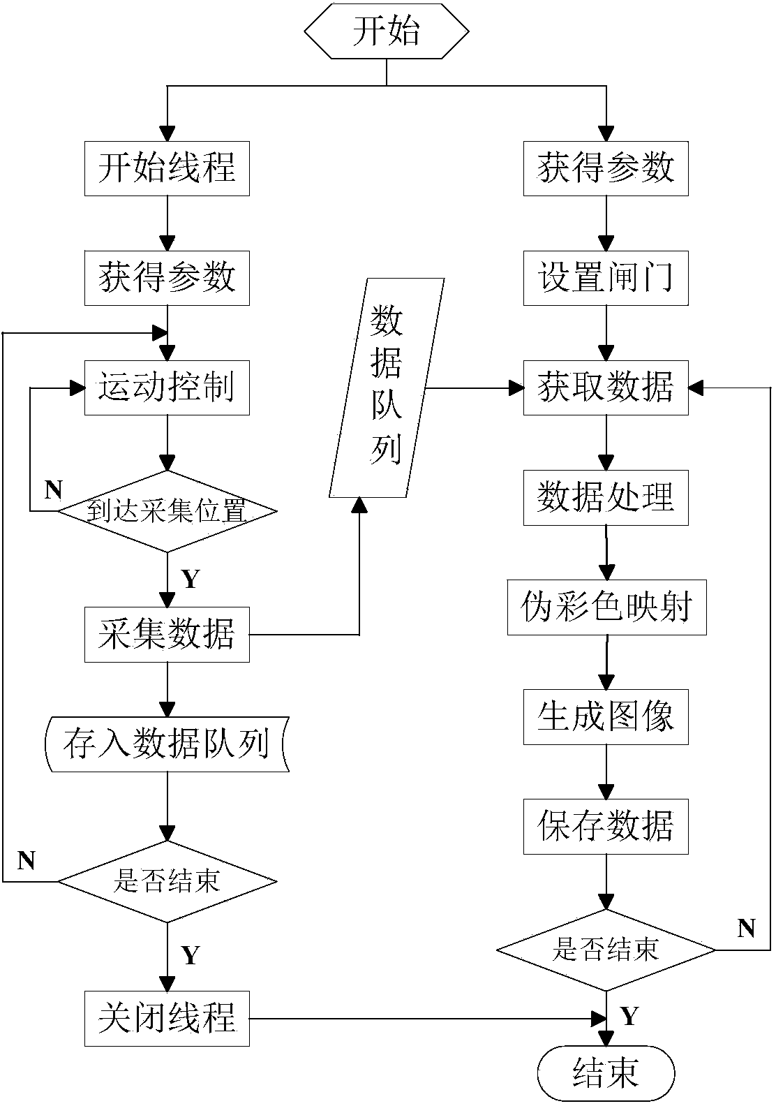

Image

  • Method for rapidly mapping and imaging pseudo-colors through ultrasonic microscopic technology
  • Method for rapidly mapping and imaging pseudo-colors through ultrasonic microscopic technology
  • Method for rapidly mapping and imaging pseudo-colors through ultrasonic microscopic technology

Examples


Embodiment Construction

[0009] The specific embodiment of the present invention is described in detail below:

[0010] 1. Adjust the position of the ultrasonic transducer in the vertical direction, find a waveform to be detected, observe the A-scan waveform and change the delay time, sampling length and voltage range appropriately, and when the peak value of the waveform reaches the maximum position, the ultrasonic transducer The detector probe is focused on the depth position to be imaged.

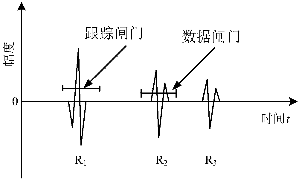
[0011] 2. If figure 1 As shown, set or drag the tracking gate with the mouse so that the tracking gate includes the surface reflected wave of the chip under test, that is, the first strong waveform. The threshold of the tracking gate should be as low as possible on the premise that it is greater than the noise signal. Then set the data gate and drag the data gate so that the data gate completely includes the waveform to be detected, and the threshold is as small as possible on the premise that it is greater tha...


PUM


Abstract

The invention relates to a method for rapidly mapping and imaging pseudo-colors through an ultrasonic microscopic technology. According to the method, high-frequency ultrasound can be used for micro-imaging of the surface and the sub-surface of the material to be tested and a fine structure in the material at a certain height. The method has the characteristics of high sensitivity, high resolution, intuitive images and the like and is suitable for the ultrasonic inspection and measurement field of electronic packaging, composite materials and medical application. The method comprises the following steps: obtaining peak data in each scanning point data gate by setting data acquisition parameters and scanning parameters of a specimen to be tested and arranging gates according to scanning signals A, transforming data values into gray values, transforming different gray values into different RGB (red, green and blue) color values according to a linear mapping function, and rapidly mapping and generating a pseudo-color image subjected to ultrasonic microscopic detection, thus relatively easily recognizing image details and the target. According to the method, a data acquisition technology, an image reconstruction technology and an automation technology are integrated, the pseudo-color ultrasonic image of the internal structure of the specimen to be tested can be obtained, and a supplementary means is provided for detecting sizes, shapes and distribution of defects existing the specimen to be tested.

Description

1. Technical field [0001] The invention belongs to the technical field of non-destructive testing, relates to the field of ultrasonic imaging, in particular to a pseudo-color rapid mapping imaging method for ultrasonic microscopic testing. 2. Background technology [0002] Ultrasonic testing technology has become a non-destructive testing technology widely used at home and abroad due to its high detection sensitivity, ability to detect internal defects of objects, wide range of detection objects, accurate defect location and low cost. Ultrasonic images can provide intuitive and a large amount of information, directly reflect the acoustic properties of objects, and display the shape of object defects, and determine their location, size and nature, and have automatic data collection, automatic data processing, automatic evaluation of results and perfect data records And other functions, so ultrasonic imaging technology is the development trend of modern ultrasonic testing. ...

Claims


Application Information

Patent Timeline
IPC IPC(8): G01N29/06
Inventor 徐春广彭凯郭祥辉肖定国樊琼杨柳
Owner BEIJING INSTITUTE OF TECHNOLOGYGY
Learn More