
Control method and device for generator set

A generator set and control system technology, applied in the field of electric power, can solve the problems of increased wear of the unit, affecting the reliability and life of the unit operation, etc.

Active Publication Date: 2014-05-21
北京睿能世纪科技有限公司
View PDF2 Cites 6 Cited by
  • Summary
  • Abstract
  • Description
  • Claims
  • Application Information

AI Technical Summary

Problems solved by technology

For example, in the AGC operation mode, increasing the output adjustment speed of the unit will cause the actuators of the unit, such as valves, to move frequently, causing increased wear and tear of the unit, and affecting the reliability and life of the unit.

Method used


Image

  • Control method and device for generator set
  • Control method and device for generator set
  • Control method and device for generator set

Examples


Embodiment 1

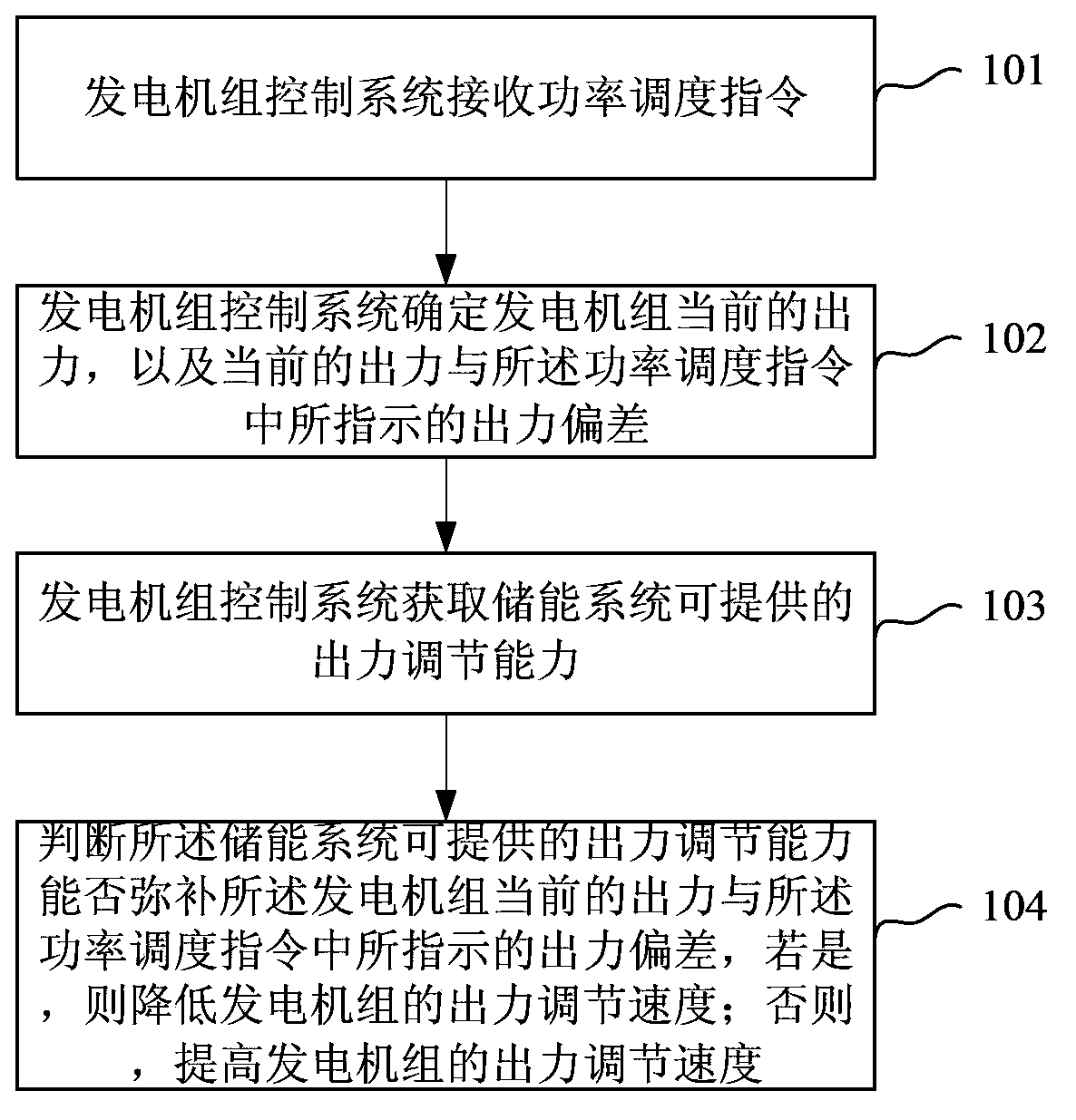
[0086] In a possible situation, if the machine-side parallel energy storage system is not in the state of cooperating with the generator set, the range of output adjustment capability that the machine-side parallel energy storage system can provide is P ess =0; if the energy storage system is currently in the state of cooperating with the generator set, and the running state is normal, then

[0087] The steps for the control system of the generating set in step 103 to obtain the current output adjustment capability of the energy storage system include:

[0088] According to the operating temperature of the energy storage system, judge

[0089] If the operating temperature of the energy storage system is within the normal operating temperature range, the output adjustment capability that the energy storage system can provide is P ess =P rate ;

[0090] If the operating temperature of the energy storage system is higher than the upper limit of the normal operating temperature...

Embodiment 2

[0102] In another possible situation, if the machine-side parallel energy storage system is not in the state of coordinating with the generator set, the range of output adjustment capability that the machine-side parallel energy storage system can provide is P ess ={0,0}; If the energy storage system is currently in the state of cooperating with the generator set, and the operating state is normal, then

[0103] The steps for the control system of the generating set in step 103 to obtain the current output adjustment capability of the energy storage system include:

[0104] According to the current state of charge of the energy storage system, judge

[0105] If the current charging state of the energy storage system is within the range of the normal charging state, the output adjustment capability that the energy storage system can provide is P ess ={P charge , P discharge},

[0106] If the current charging state of the energy storage system is higher than the upper limit ...


PUM


Abstract

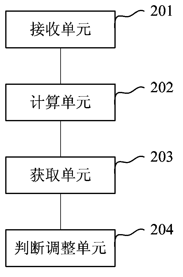
The application discloses a control method of a generator set and is applied to a power generation system. The power generation system comprises the generator set for generating output power, a generator set control system for controlling the generator set and an energy storage system for matching with the generator set in operation. The control method of the generator set is characterized in that the generator set control system determines whether the output power adjustment capacity which the energy storage system can provide can make up the deviation between the current output power of the generator set and the output power indicated in a power dispatch instruction when the energy storage system currently is in a state of matching with the generator set in operation and the operation state is normal, if so, the output power adjustment speed of the generator set is reduced, and if not, the output power adjustment speed of the generator set is improved. By means of the control method of the generator set, advantages of the generator set and the energy storage system are fully taken advantage of, the loss and abrasion of the generator set can be reduced, meanwhile, the response effects of the power dispatch instructions can be guaranteed, and the economy, stability and reliability of set operation can be improved.

Description

technical field [0001] The invention relates to the field of electric power technology, in particular to a method and device for controlling a generating set. Background technique [0002] The power system includes the power grid, generators that provide power, and various electrical equipment. Automatic generation control (AGC) is a basic function in the dispatch automation system, which plays a vital role in ensuring the frequency quality of the power grid and the constant exchange power of tie lines. [0003] Due to the limitations of the traditional generator set's own characteristics, when responding to the AGC command of the power grid, it is usually necessary to change the control mode of the generator set to increase the output adjustment speed of the generator set and improve the response performance of the AGC command to meet the requirements of the grid dispatching for the generator set adjustment speed. requirements. For example, increase the output adjustment ...

Claims


Application Information

Patent Timeline
Patent Type & Authority Applications(China)
IPC IPC(8): H02J3/46
Inventor 薛飞王澍牟镠峰
Owner 北京睿能世纪科技有限公司
Learn More