

Rotary iron ore analyzing device
An analysis device and iron ore technology, applied in the direction of analysis materials, instruments, etc., can solve the problems of inconvenient hand-holding, low detection efficiency, heavy workload, etc., and achieve the effect of simple structure, high degree of automation, and accurate sampling
- Summary
- Abstract
- Description
- Claims
- Application Information
AI Technical Summary
Problems solved by technology
Method used
Image

Examples
Embodiment 1
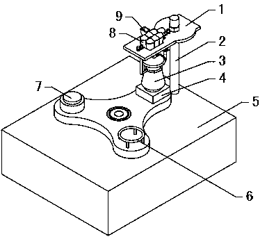
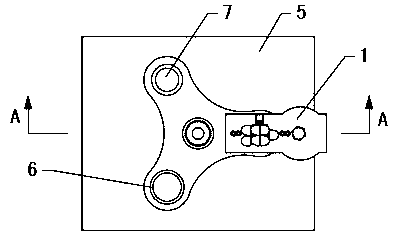
[0041] refer to figure 1 , a rotary iron ore analysis device, including a rotary table, a fixed table 1 and a flask 3, a weighing platform 4, a cooling platform 6 and a heating platform 7 are arranged at intervals on the circumference of the rotary table, and the rotary table is fixed on the base 5 On the side, the flask 3 is placed on the weighing platform 4 of the rotary workbench, the fixed workbench 1 is horizontally fixed above the flask 3 through the support column 2, and the fixed workbench 1 is fixed with a plurality of reagent dropping bottles 8 containing titration reagents and a The sample box 9 for holding the iron ore sample, the lower opening of the reagent dropping bottle 8 and the sample box 9 are all located above the opening of the flask 3, and the fixed workbench 1 is also fixed with a flask clamping mechanism, which is tightened and closed. The flask 3 is lifted, the rotary table rotates one or more stations, and the flask clamping mechanism makes the flask...
Embodiment 2
[0068] refer to Figure 10, the left clamp arm 14 and the right clamp arm 15 are respectively sleeved with a plurality of free-rotating rings 24, the left clamp arm 14 and the right clamp arm 15 swing relatively, and are clamped on the upper side of the V-shaped bottleneck of the flask 3, the flask When the V-shaped neck of the bottle 3 is squeezed and slides upwards, the ring 24 rotates with the rise of the flask 3, preventing the large sliding friction force between the flask 3 and the left clamp arm 14 and the right clamp arm 15, reducing the Friction, making it easier for flask 3 to rise.
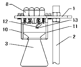
[0069] refer to Figure 11 , the upper opening of the reagent drop bottle 8 is sealed with a capsule 16. Even if there is a certain gap between the distribution shaft 18 and the reagent drop bottle 8 due to processing, the negative pressure produced by the capsule 16 can ensure that the reagent will not fall freely. It can fall from the dispensing groove 19, further ensuring the accur...
Embodiment 3
[0071] refer to Figure 12 , a cooling fan 28 is installed on the cooling platform 6 of the rotary table, and the flask 3 is placed on the upper side of the cooling fan 28. When cooling is required, the cooling fan 28 works to cool the solution in the flask 3 rapidly and improve detection efficiency. Other structures are with embodiment 1.
PUM
 Abstract
Description
Claims
Application Information