Near-field focusing planar array antenna

A planar array antenna and near-field focusing technology, which is applied to the structural form of antennas, electrical components, and radiation elements, can solve the problems of miniaturization, high efficiency, and low cost, and achieve miniaturization and excellent performance. , the effect that the performance will not deteriorate

Inactive Publication Date: 2014-05-28
UNIV OF ELECTRONICS SCI & TECH OF CHINA
View PDF7 Cites 13 Cited by
  • Summary
  • Abstract
  • Description
  • Claims
  • Application Information

AI Technical Summary

Problems solved by technology

[0007] Although the processing and design of the above two typical focus array antennas are relatively simple, and the

Method used


Image

  • Near-field focusing planar array antenna
  • Near-field focusing planar array antenna
  • Near-field focusing planar array antenna

Examples


Embodiment

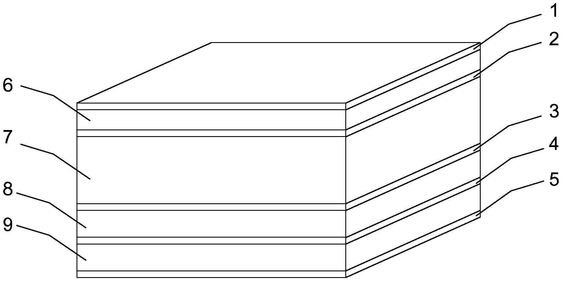
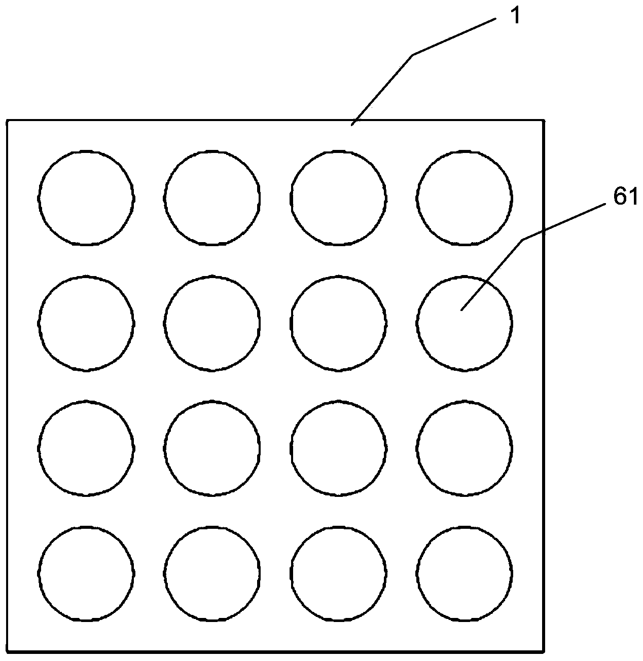
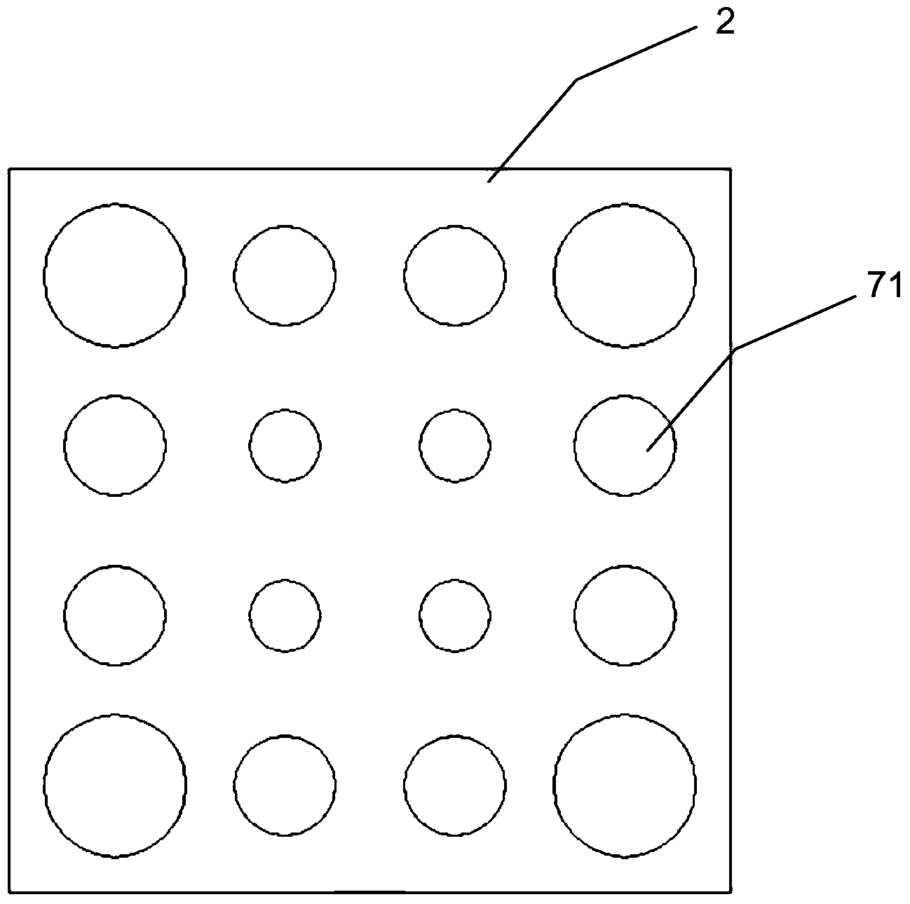
[0031] In this embodiment, the center frequency of the near-field focusing planar array antenna is 10 GHz, and the first dielectric layer 6 and the second dielectric layer 7 are made of FR4 material with a dielectric constant of 4.5, and the thickness of the first dielectric layer 6 is 1.6mm, the thickness of the second dielectric layer 7 is 6.4mm. The third dielectric layer 8 and the fourth dielectric layer 9 are made of RF35 material with a dielectric constant of 3.5 and a loss tangent of 0.0018. The third dielectric layer 8 The thickness of the fourth dielectric layer 9 is 1.52mm, and the thickness of the fourth dielectric layer 9 is 0.508mm; the diameter of the metallized radiation hole 61 and the metallized transition hole 81 is 18mm; the distance from the array center is from far to near. 18 mm, 18.8 mm, and 20 mm in sequence, the width of the substrate integrated waveguide unit is 10 mm, the diameter of the metallized through hole 91 is 0.5 mm, and the center-to-hole dis...


PUM

PropertyMeasurementUnit
Thicknessaaaaaaaaaa
Thicknessaaaaaaaaaa
Thicknessaaaaaaaaaa

Abstract

The invention discloses a near-field focusing planar array antenna which is high in efficiency, small in size and low in cost. The near-field focusing planar array antenna comprises a first copper-coated metal layer, a first medium layer, a second copper-coated metal layer, a second medium layer, a third copper-coated metal layer, a third medium layer, a fourth copper-coated metal layer, a fourth medium layer and a fifth copper-coated metal layer, wherein the first copper-coated metal layer, the first medium layer, the second copper-coated metal layer, the second medium layer, the third copper-coated metal layer, the third medium layer, the fourth copper-coated metal layer, the fourth medium layer and the fifth copper-coated metal layer are sequentially laminated from top to bottom. Metallized radiation holes are formed in the first medium layer. Metallized phase shift holes are formed in the second medium layer. Metallized transition holes are formed in the third medium layer. A substrate-integrated waveguide parallel feed network is arranged on the fourth medium layer. According to the near-field focusing planar array antenna, phase compensation is achieved through the metallized phase shift holes, the compensation range is wide, the structure is simple, performance is excellent, efficiency of the antenna is high, the size of the antenna can be greatly reduced, and cost can be reduced; in addition, different focusing positions can be adjusted. The near-field focusing planar array antenna is suitable for being popularized and applied in the technical field of microwave antennas and millimeter wave antennas.

Description

technical field [0001] The invention relates to the technical field of microwave and millimeter wave antennas, in particular to a near-field focusing planar array antenna. Background technique [0002] With its electromagnetic wave focusing effect, the point-focus antenna is widely used in microwave and millimeter wave imaging, wireless energy transmission, radio frequency wireless identification, microwave medical treatment and other occasions. [0003] Traditional focusing antennas can be divided into two categories according to their shapes: non-planar focusing antennas and planar focusing antennas. Among them, non-planar focusing antennas include parabolic antennas and dielectric lens antennas; planar focusing antennas are mainly patch array antennas. [0004] Traditional non-planar focusing antennas, such as parabolic antennas, dielectric lens antennas, etc., can achieve better focusing characteristics, but due to the non-planar structure of the antenna, precise machin...

Claims


Application Information

Patent Timeline
IPC IPC(8): H01Q1/38H01Q3/30
Inventor 程钰间王磊黄伟娜吴杰
Owner UNIV OF ELECTRONICS SCI & TECH OF CHINA
Why Eureka
Try Eureka