
Divide-by-two frequency divider circuit based on current mirror switching logic

A two-frequency divider and switching logic technology, applied in the direction of electrical components, automatic power control, etc., can solve the problems of increasing chip power consumption and chip area, and achieve reduced chip area, small power consumption, and anti-interference ability. high effect

Active Publication Date: 2017-01-18
WUXI XINXIANG ELECTRONICS TECH
View PDF7 Cites 0 Cited by
  • Summary
  • Abstract
  • Description
  • Claims
  • Application Information

AI Technical Summary

Problems solved by technology

However, compared with the traditional structure, the structure proposed in this patent adds 4 MOS transistors. The increase of MOS transistors will undoubtedly increase the area of ​​the chip, and on the other hand, it will also increase the power consumption of the chip.

Method used


Image

  • Divide-by-two frequency divider circuit based on current mirror switching logic
  • Divide-by-two frequency divider circuit based on current mirror switching logic
  • Divide-by-two frequency divider circuit based on current mirror switching logic

Examples


Embodiment Construction

[0029] Below in conjunction with accompanying drawing, the technical scheme of invention is described in detail:

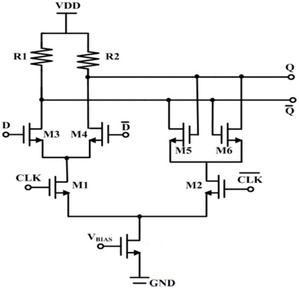
[0030] figure 1 The output port Q of the D flip-flop in the traditional CML architecture of the differential positive-phase frequency division signal Q and the output port QN of the Q-channel differential negative-phase frequency division signal use two load resistors R1 and R2. Due to the limited resistance of the load resistance , so that the maximum output swing of the Q-way differential positive-phase frequency division signal output port Q and the Q-way differential negative-phase frequency division signal output port QN is also limited (the maximum output voltage swing of the traditional structure=load resistance*tail current / 2).

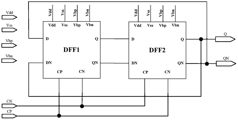
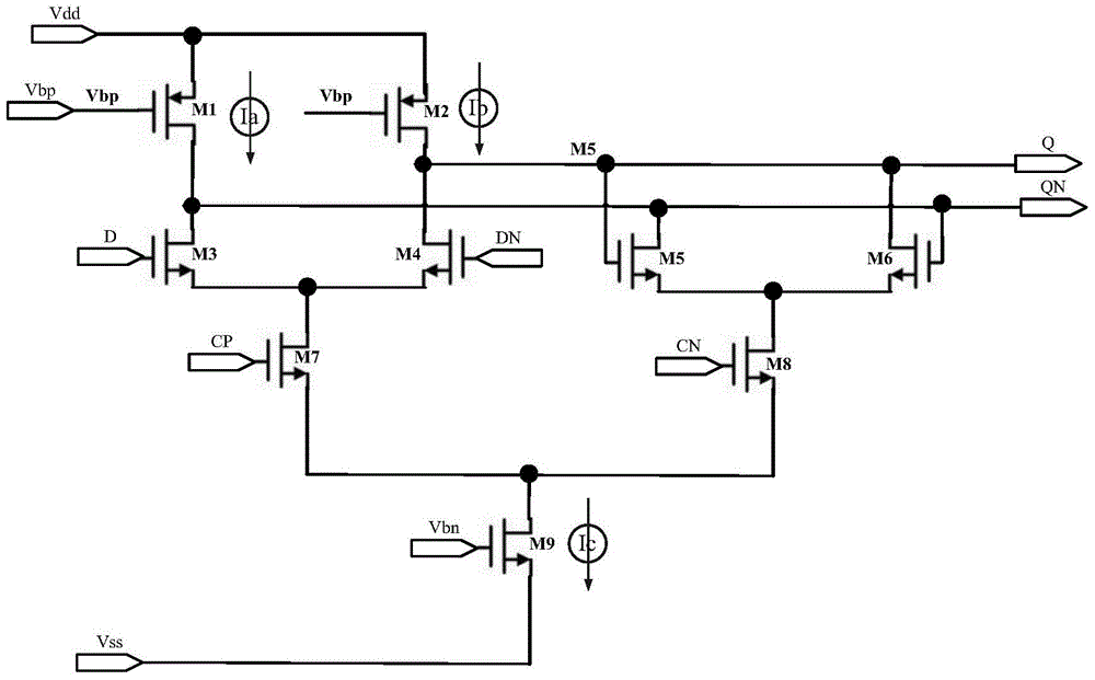
[0031] The divide-by-two frequency divider circuit based on current mirror switching logic disclosed by the present invention is as follows: figure 2 As shown, including: power supply positive input port Vdd, power supply negati...


PUM


Abstract

The invention discloses a dividing two frequency divider circuit based on current mirror switch logic, which belongs to the technical field of integrated circuits. The dividing two frequency divider circuit comprises a power supply positive input port, a power supply negative input port, a differential clock positive phase signal input port, a differential clock negative phase signal input port, a differential positive phase data signal input port, a differential negative phase data signal input port, a Q path differential positive phase frequency dividing signal output port, a Q path differential negative phase frequency dividing signal output port, a PMOS tube current mirror bias voltage input port, an NMOS tube current mirror bias voltage input port, and two D triggers. A PMOS tube is used to replace a load resistor in a traditional dividing two frequency divider, which reduces the area of a chip. An active device is used to replace a passive device, which avoids the defect that the resistor is used as a kind of conduction of a current mirror switch. Two PMOS tubes are alternately turned on, which reduces power consumption at the same frequency under the condition of low voltage. The circuit has the advantages of low noise, high anti-interference ability, and wide frequency input range.

Description

technical field [0001] The invention relates to a divide-by-two frequency divider circuit based on current mirror switch logic, and belongs to the technical field of integrated circuits. Background technique [0002] With the development of the integrated circuit industry and the continuous improvement of CMOS circuit manufacturing technology, wireless communication equipment manufactured using CMOS technology has also undergone tremendous changes. These changes have become the development trend of wireless communication technology in the next stage for high frequency and low power consumption. Lay the groundwork. [0003] At this stage, the transceiver of wireless communication technology is mainly implemented by a phase-locked loop frequency synthesizer. The frequency of the phase-locked loop is composed of a voltage-controlled oscillator (VCO, Voltage Controlled Oscillator) and a prescaler. Frequency conversion and down conversion functions. In this synthesizer, a modul...

Claims


Application Information

Patent Timeline
Patent Type & Authority Patents(China)
IPC IPC(8): H03L7/18
Inventor 周烨周金风季海梅章志莹李芳芳占健
Owner WUXI XINXIANG ELECTRONICS TECH
Learn More