
Automatic spraying device capable of walking and spraying method thereof

A technology of automatic spraying and traveling wheels, applied in spraying devices, buildings, building structures, etc., can solve the problems of controlled work place, uneven spraying, loss of competitiveness, etc., and reduce uncertain factors and construction time. The effect of saving and reducing personal injury

Active Publication Date: 2014-06-04
CHINA MCC5 GROUP CORP
View PDF7 Cites 17 Cited by
  • Summary
  • Abstract
  • Description
  • Claims
  • Application Information

AI Technical Summary

Problems solved by technology

[0005] In general, when spraying, due to manual operation, it is easy to cause uneven spraying, and it is easy to cause certain injuries to the person.
When spraying some roads or bridges, due to the constraints of the construction environment, when manual operations cannot be performed, the current steel structure processing plants and some components on the construction site are sprayed manually, and the construction quality is not easy to control, and it is easy to cause missed spraying. , flow and other phenomena, the quality of construction has very high requirements on the quality of operators, and products with large quality differences will also be produced, which will lose the competitiveness of many markets
Moreover, when spraying manually, even if you wear certain protective equipment, long-term construction will cause certain harm to the human body.
The construction method commonly used in the market now has the characteristics of difficult construction quality control, high requirements for operators, long working hours, and controlled working place. It is necessary to improve a new spraying equipment to avoid the above problems.

Method used


Image

  • Automatic spraying device capable of walking and spraying method thereof
  • Automatic spraying device capable of walking and spraying method thereof
  • Automatic spraying device capable of walking and spraying method thereof

Examples


Embodiment 1

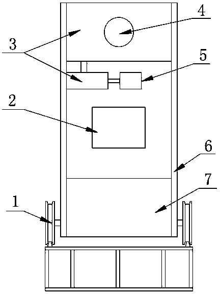
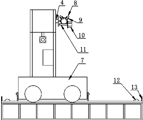
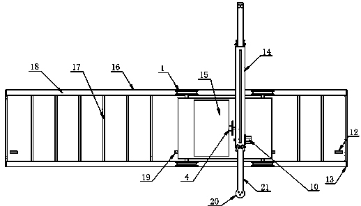
[0031] Such as figure 1 , figure 2 , image 3 As shown, the automatic spraying device capable of walking includes a car body 7 and a slide rail 16 arranged below the car body 7, the car body 7 can move along the slide rail 16, and the car body 7 is provided with a support frame 6, and The inside of the support frame 6 is provided with a control integration box 2 and a bipolar transmission gearbox 3 that can move in the vertical direction inside the support frame 6. The bipolar transmission gearbox 3 is connected with an internal hollow support tube 14, and the support tube 14 Set outside the support frame 6, the two ends of the support tube 14 are all provided with a support wheel set, the inside of the support tube 14 is provided with a spraying rod 21, and the two ends of the spray rod 21 extend out of the two ends of the support tube 14 respectively, One end of the pipe 14 is provided with a rotating tooth 11 , and the spraying rod 21 meshes with the rotating tooth 11 , ...

Embodiment 2

[0048] The structure of embodiment 2 is basically the same as that of embodiment 1, and the method of spraying in the horizontal direction is adopted: the telescopic motor is turned on to drive the rotation of the rotating gear, and through the meshing of the rotating gear and the tooth mark of the spraying rod, the horizontal movement of the spraying rod is driven to change the rotation of the rotating gear. The direction of rotation, the horizontal movement direction of the spray rod also changes, and the spray gun can spray in the horizontal direction.

[0049] The rotating gear 11 is a device driven by a telescopic motor. The rotating gear 11 is always in mesh with the spraying rod 21. When the rotating gear 11 is driven, the tooth marks at the bottom of the spraying rod 21 engage with the rotating gear 11 in the horizontal direction, slowly driving the spraying The rod 21 is sprayed in the horizontal direction, the length of the spray rod is 4 meters, and the spraying dist...

Embodiment 3

[0053] Fan-surface spraying: Run step (a) and step (b) at the same time to achieve fan-surface spraying effect. In the case of simultaneous movement of the bipolar transmission gearbox and the rotating gear, the trajectory of the spraying rod is a parabola, and the trajectory of the entire spray gun is a fan-shaped surface. The movement of the walking trolley on the slide rail drives the spraying device to perform spraying at different positions. spraying.

[0054] When the bipolar gear box and the rotating gear move at the same time, the spraying rod moves both vertically and horizontally, and the effect of spraying in the spray gun is parabolic. Using its own weight and the continuous impact force of the spray gun, the whole All the walls can be sprayed in place, which reduces the trouble of multiple spraying back and forth and improves the construction efficiency.

[0055] The walking trolley walks on the slide rail and moves along the track of the rail. The wheel surface ...


PUM


Abstract

The invention discloses an automatic spraying device capable of walking and a spraying method thereof. The automatic spraying device comprises a trolley body and a sliding rail. A supporting frame is arranged on the trolley body and provided with a control integration box and a double-pole speed change gear box. The double-pole speed change gear box is connected with a supporting tube. The supporting tube is provided with a supporting wheel set. A spraying rod is arranged inside the supporting tube. The supporting tube is provided with a rotating gear. The spraying rod is meshed with the rotating gear. The rotating gear is connected with a telescopic motor which is fixed to the supporting tube. An operator holds a remote controller by hand to enable signals to be transmitted to the control integration box and control the motor to drive the double-pole speed change gear box to rotate. The double-pole speed change gear box moves up and down, then the spraying rod moves in the perpendicular direction, and a spraying gun conducts spraying in the perpendicular direction. According to the automatic spraying device and the spraying method of the automatic spraying device, a trolley moves on the sliding rail to spray the face needing to be sprayed evenly in cooperation with the up-down and left-right movement of a telescopic rod, automated control is adopted, labor intensity is reduced, and working efficiency is improved.

Description

technical field [0001] The invention relates to spraying, in particular to a walking automatic spraying device and a spraying method thereof, belonging to the field of building construction. Background technique [0002] Spraying is a coating method in which spray guns or disc atomizers are dispersed into uniform and fine droplets by means of pressure or centrifugal force and applied to the surface of the object to be coated. It can be divided into air spraying, airless spraying, electrostatic spraying and various derived methods of the above basic spraying forms, such as large flow and low pressure atomization spraying, thermal spraying, automatic spraying, multi-group spraying, etc. [0003] The spraying operation has high production efficiency and is suitable for manual operation and industrial automation production. It is widely used in hardware, plastics, furniture, military industry, ships, construction and other fields. It is the most commonly used coating method toda...

Claims


Application Information

Patent Timeline
IPC IPC(8): B05B13/04B05B15/10E04F21/08
CPCB05B13/04B05B13/041B05B15/60
Inventor 高长玲谢珲
Owner CHINA MCC5 GROUP CORP
Features
  • Generate Ideas
  • Intellectual Property
  • Life Sciences
  • Materials
  • Tech Scout
  • Unparalleled Data Quality
  • Higher Quality Content
  • 60% Fewer Hallucinations
Learn More