Method for laser marking metal surface with desired colour

A metal surface, laser marking technology, applied in the direction of copying/marking method, laser welding equipment, metal processing equipment, etc., can solve the problems of inconvenient anodization of metal copper, inability to carry out, unable to produce color, etc.

Active Publication Date: 2014-06-04
SPI LASERS UK
View PDF8 Cites 11 Cited by
  • Summary
  • Abstract
  • Description
  • Claims
  • Application Information

AI Technical Summary

Problems solved by technology

[0004] Metal copper is not convenient for anodizing
Laser marking that relies on oxide layers is therefore difficult or impossible in copper and alloys such as brass and bronze
Laser marking has been achi

Method used


Image

  • Method for laser marking metal surface with desired colour
  • Method for laser marking metal surface with desired colour
  • Method for laser marking metal surface with desired colour

Examples


Embodiment

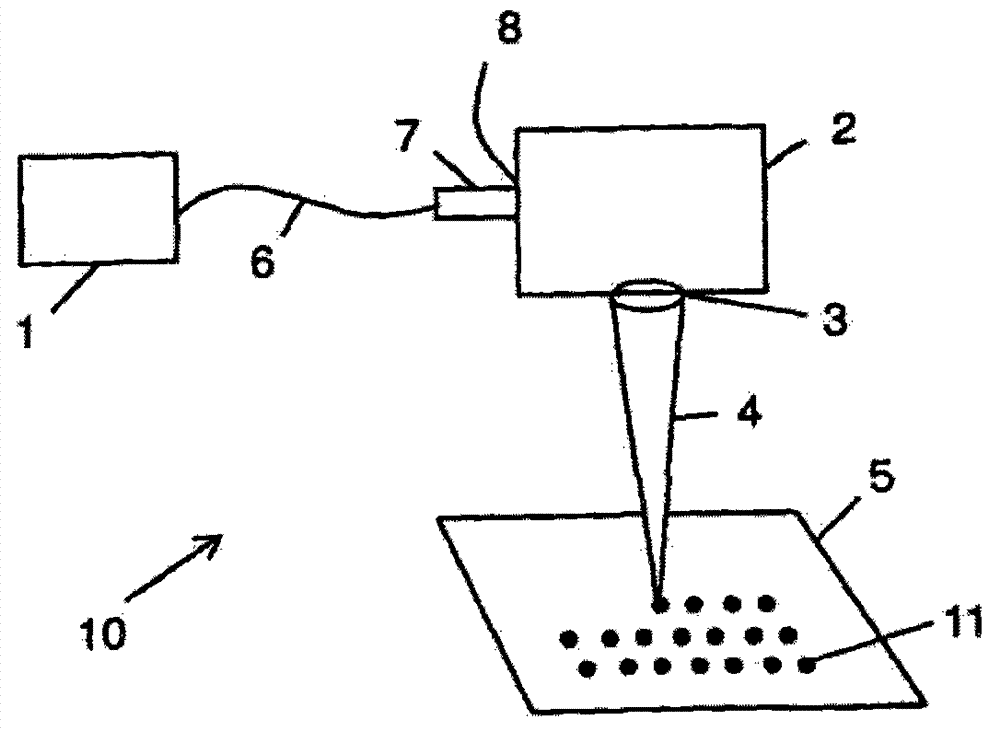
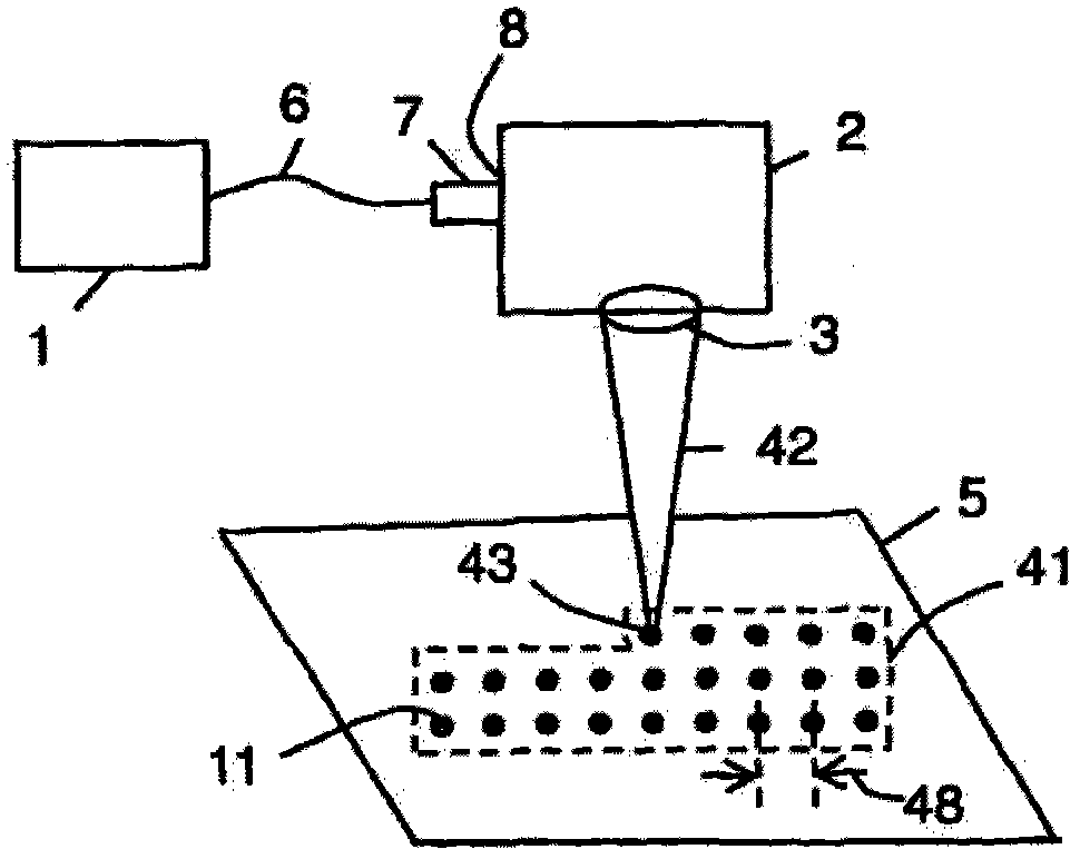
[0061] in the attached Figure 4 , 5 The laser 1 described in is an air-cooled pulsed 20w laser of model G4HS-L produced by SPI Lasers UK Ltd of Southampton, UK. The scanning device 2 is a galvanometer scanning head (also referred to as a scanner) of the model SuperScan II produced by Raylase GmbH in Wessling, Germany. The objective lens 3 is an objective lens with a focal length f-theta of 163 mm. The first laser beam 42 and the second laser beam 52 are transmitted from the laser 1 to the scanning device 2 via a 75mm beam expander collimator (BEC) 7, which can make the laser beams pass through the scanning head entrance 8. With 8mm (1 / e 2 ) of the nominal diameter. This results in a laser beam waist diameter 34 of 50+ / −5.0 μm at the focal plane of the scanner objective 3 . During normal operation of the workstation, the target metal surface 5 is placed at or near the focal plane.

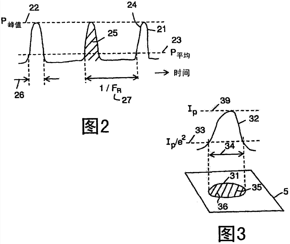
[0062] The laser 1 is capable of generating pulses in the nanosecond range (between appro...


PUM

PropertyMeasurementUnit
Peak poweraaaaaaaaaa

Abstract

A method for laser marking a metal surface (5) with a desired colour, which comprises forming at least one first pattern (41) on a metal surface (5) with a first laser beam (42) having a first pulse fluence (43), forming at least one second pattern (51) on the metal surface with a second laser beam (52) having a second pulse fluence (53), characterized by causing the second pattern (51) to overlay the first pattern (41), arranging the first pulse fluence (43) to be at least five times greater than the second pulse fluence (53), the colour being given by the first and second pulse fluences (43, 53) and spot spacings (48) in the first and second patterns (41, 51), and selecting the first and second pulse fluences (43, 53) and the spot spacings (48) to form the desired colour.

Description

technical field [0001] The invention relates to a method of laser marking a metal surface with a desired color. The present invention is particularly suitable for color marking of non-anodized metal surfaces without the use of dyes, inks or other chemicals. Background technique [0002] The use of dyes, inks, and other chemicals to color-code commercial, consumer, and industrial supplies is heavily dependent on factors such as supply chain, logistics, and the environment. A process that enables color marking without the use of dyes, inks and other chemicals would therefore have significant advantages. [0003] Laser color marking has been applied to many materials, including metals, and once a specific material is found for a perfect match, the laser marking process is usually reliable, repeatable, and verifiable for high-volume, high-yield production. An example is the color marking of anodized aluminum, a material that is widely used due to its light weight, high strengt...

Claims


Application Information

Patent Timeline
IPC IPC(8): B23K26/354
CPCB23K26/0081B41M5/262B23K26/0009B23K26/0084B23K26/0066B23K26/0006B23K26/352B23K26/354B23K26/355B23K2103/50
Inventor P·哈里森
Owner SPI LASERS UK
Why Eureka
Try Eureka