
Pile-forming device and method for vortex pressing extruding and expanding concrete layering expanding uplift pile

A technology of concrete and uplift piles, applied in sheet pile wall, construction, infrastructure engineering and other directions, can solve the problems of unguaranteed uplift quality, unsatisfactory bearing capacity, low efficiency, etc. The effect of improving the pull-out bearing capacity and improving the longitudinal and lateral strength

Inactive Publication Date: 2014-06-04
CHINA UNIV OF PETROLEUM (EAST CHINA)
View PDF6 Cites 0 Cited by
  • Summary
  • Abstract
  • Description
  • Claims
  • Application Information

AI Technical Summary

Problems solved by technology

The current method of anti-uplift piles, when the uplift-resistant piles are pulled out, is mainly due to the force of the steel bars inside the pile and the side friction resistance between the pile body and the soil, so the welding quality of the pile connection and the steel cage is high, so the quality of the pull-out resistance cannot be guaranteed. , the bearing capacity will not meet the requirements, and it is not economical; and most of the existing methods need to take the original soil, which is divided into mechanical and manual digging, and the efficiency is relatively low

Method used


Image

  • Pile-forming device and method for vortex pressing extruding and expanding concrete layering expanding uplift pile
  • Pile-forming device and method for vortex pressing extruding and expanding concrete layering expanding uplift pile
  • Pile-forming device and method for vortex pressing extruding and expanding concrete layering expanding uplift pile

Examples


Embodiment Construction

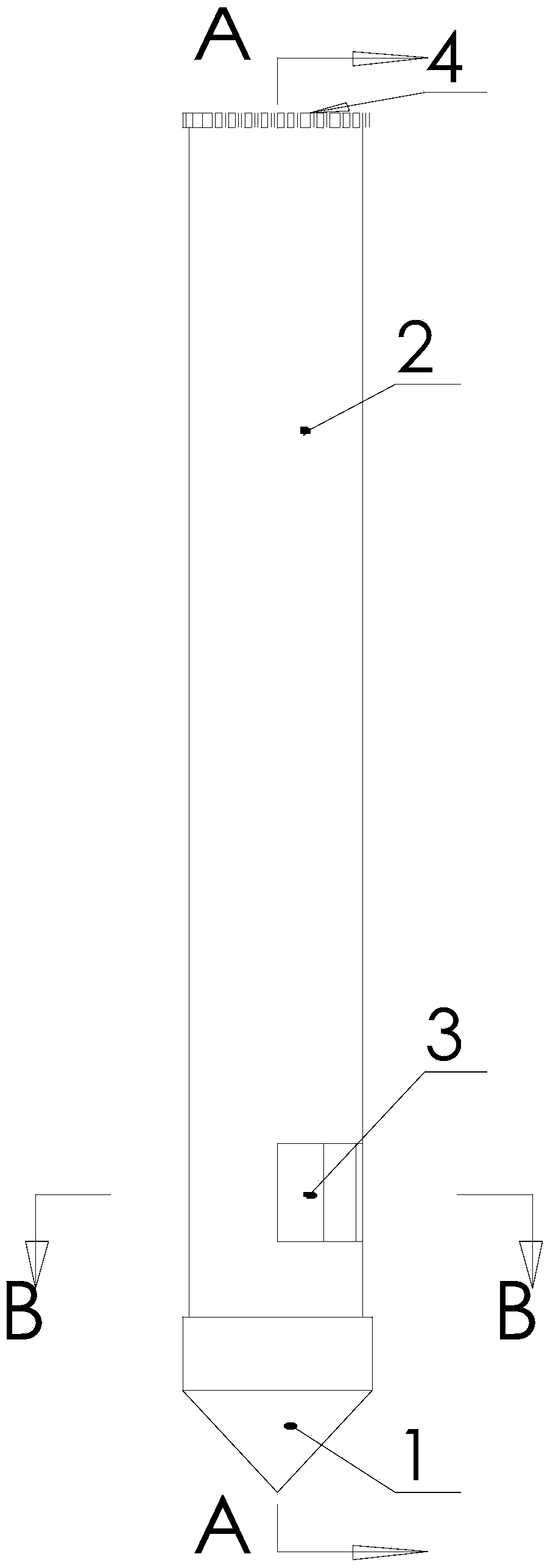
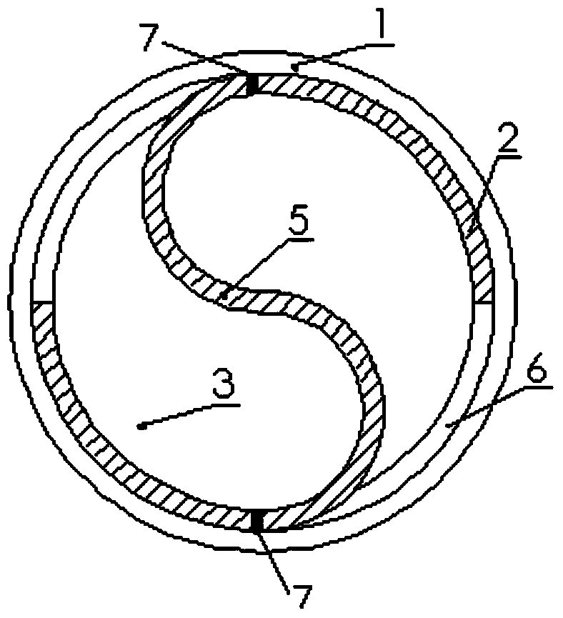
[0029] Such as Figure 1 to Figure 2 As shown, the pile-forming equipment of vortex squeezed and expanded concrete layered diameter-expanded uplift piles includes: prefabricated concrete pile head 1, steel casing 2, rotating gear 4, vortex blade 5, H-shaped steel 8 with anchor 9 The precast concrete pile head 1 is arranged at the bottom of the steel casing, the rotating gear 4 is installed on the top of the precast concrete pile head 1, and the vortex pressure blade 5 is installed at the opening of the steel casing; wherein:

[0030] The prefabricated concrete pile head 1 has a cone at the bottom and a cylinder at the top, and a cylindrical boss is formed at the top of the cylinder.

[0031] The steel casing 2 is a metal round pipe, and the inner diameter of the steel casing 2 is slightly larger than the outer diameter of the cylindrical boss of the precast concrete pile head 1, so as to ensure that the top of the precast concrete pile head 1 can just be embedded in the steel ...


PUM


Abstract

The invention belongs to the field of geotechnical engineering, and particularly relates to a pile-forming device and method for a vortex pressing extruding and expanding concrete layering expanding uplift pile. The pile-forming device comprises a precast concrete pile head, a steel sleeve, a rotation gear, a vortex pressing blade and H-shaped steel. The precast concrete pile head is arranged at the bottom of the steel sleeve, the rotation gear is installed on the top of the precast concrete pile head, and the vortex pressing blade is installed in an opening of the steel sleeve. Compared with the prior art, the pile-forming device has the advantages that the steel sleeve can be recycled, construction is easy, original soil does not need to be excavated, the construction time is shortened, and the manufacturing cost is reduced; an expanding part is formed so that the overall meshing force of a pile body and the soil body can be improved, and the uplift bearing capacity can be improved; the soil body around the uplift pile can be extruded tightly, and the longitudinal and transverse strength of the soil body can be greatly improved; the bond stress between the H-shaped steel and concrete is improved through anchoring parts symmetrically arranged in the axis direction of an H-shaped steel web; the method is suitable for various viscidity soil and sand soil; layering expanding can be carried out, and the key problem that quality cannot be guaranteed through traditional expanding construction is solved.

Description

technical field [0001] The invention belongs to the field of geotechnical engineering, and in particular relates to a pile-forming device and method for layered-diameter-expanded uplift-resistant piles of vortex-pressed squeezed-expanded concrete. Background technique [0002] Pull-out piles are widely used in anti-floating of large basements, pull-out resistance of high-rise buildings (structures), pull-out resistance of offshore wharf platforms, anchor pile foundations of suspension bridges and cable-stayed bridges, pile foundations of large dock floors and static load test piles. Anchor pile foundations, etc., are generally considered for wind loads and earthquake loads. In areas with a high groundwater level, when the load on the upper structure cannot balance the buoyancy of the groundwater, the whole or part of the structure will be affected by an upward force, such as underground pools, basement structures of buildings, and biochemical pools of sewage treatment plants...

Claims


Application Information

Patent Timeline
Patent Type & Authority Applications(China)
IPC IPC(8): E02D5/46E02D15/04
Inventor 李春宝薛世峰刘晓辉
Owner CHINA UNIV OF PETROLEUM (EAST CHINA)
Learn More